Cabinet Construction

April 24th, 2006 by Keith Neufeld

While Andrea’s been working on editing video and searching for materials, I’ve been slowly building the cabinet that will house the project–and too busy to upload all my pictures. Here’s an overview of the process.

Large Sheets of Plywood

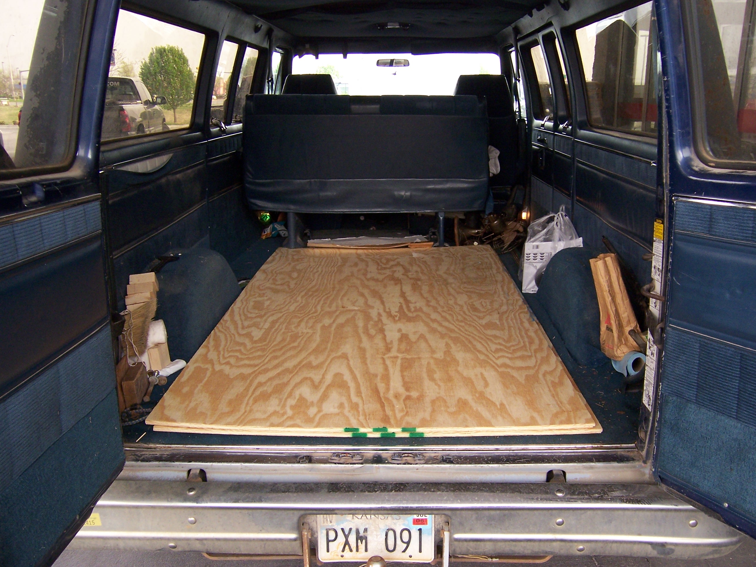
It all started a little over two weeks ago, at Lowe’s with two sheets of 15/32″ plywood in the back of the Possum Van. The cabinet is about the size of an arcade game, and they’re normally made from ~3/4″ plywood; but this won’t have to stand up to the same kind of abuse they take, so I figured ~1/2″ would be fine. It also reduces the weight dramatically, making it less difficult to lug around.

Plywood in the Back of the Van

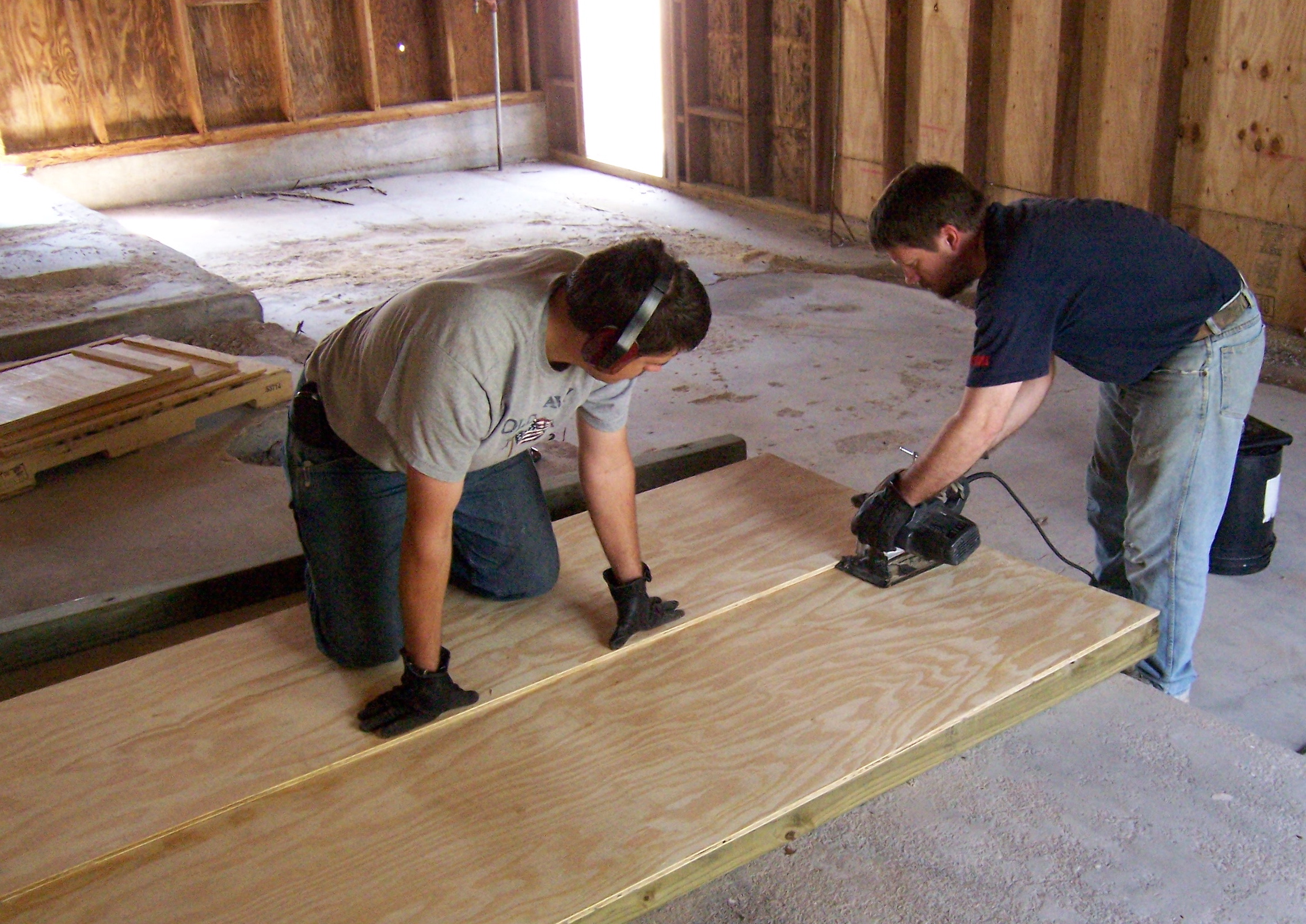
A friend and his son helped with some of the initial cuts. Because my tablesaw isn’t very accessible, and I don’t have an extension table anyway, we were cutting plywood on the floor (on 4×4 supports) using my circular saw, and the factory edge of another plywood sheet as a guide. I picked up a new Freud blade for under $15, and it’s incredible–very sharp, very easy to push, very clean cuts. We were all amazed. No more $7 Piranha blades for me!

Ripping Plywood

Starting the Base

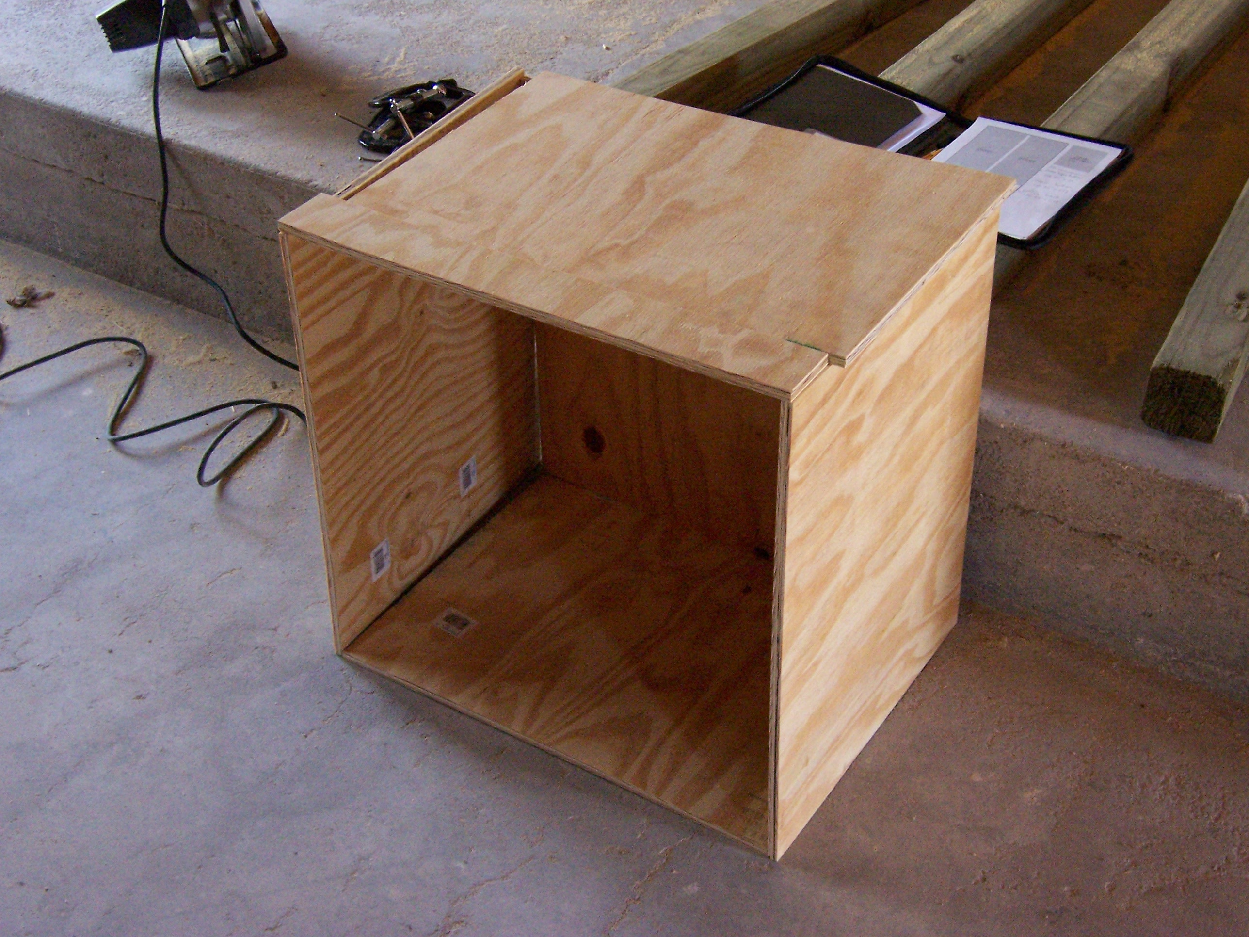
For load-bearing elements (the top and bottom of the base cabinet, the bottom of the upper cabinet, and the inner back of the upper cabinet), I used 3/4″ plywood that I had on hand. After cutting all the pieces for the base, I leaned them together to make sure they were sized correctly to fit the way I intended.

Cabinet Base Leaned Together

Not shown here is assembly of the cabinet pieces. I used my biscuit joiner for the whole thing. The biscuit joiner is basically an angle grinder with a very small (3″) circular saw blade and a fancy fence. You hold it up against the edge of a board, squeeze the trigger, and push it against the wood; it cuts a little slot in the wood. You repeat that on the opposing edge that you want to join; then take “biscuits,” little pieces of compressed beechwood that look like flattened footballs, jam them into the slots with glue, and have a pretty solid joint with (theoretically) perfect alignment. Since I was working alone most of the time, it would have been difficult to shoot a picture of the biscuiting process.

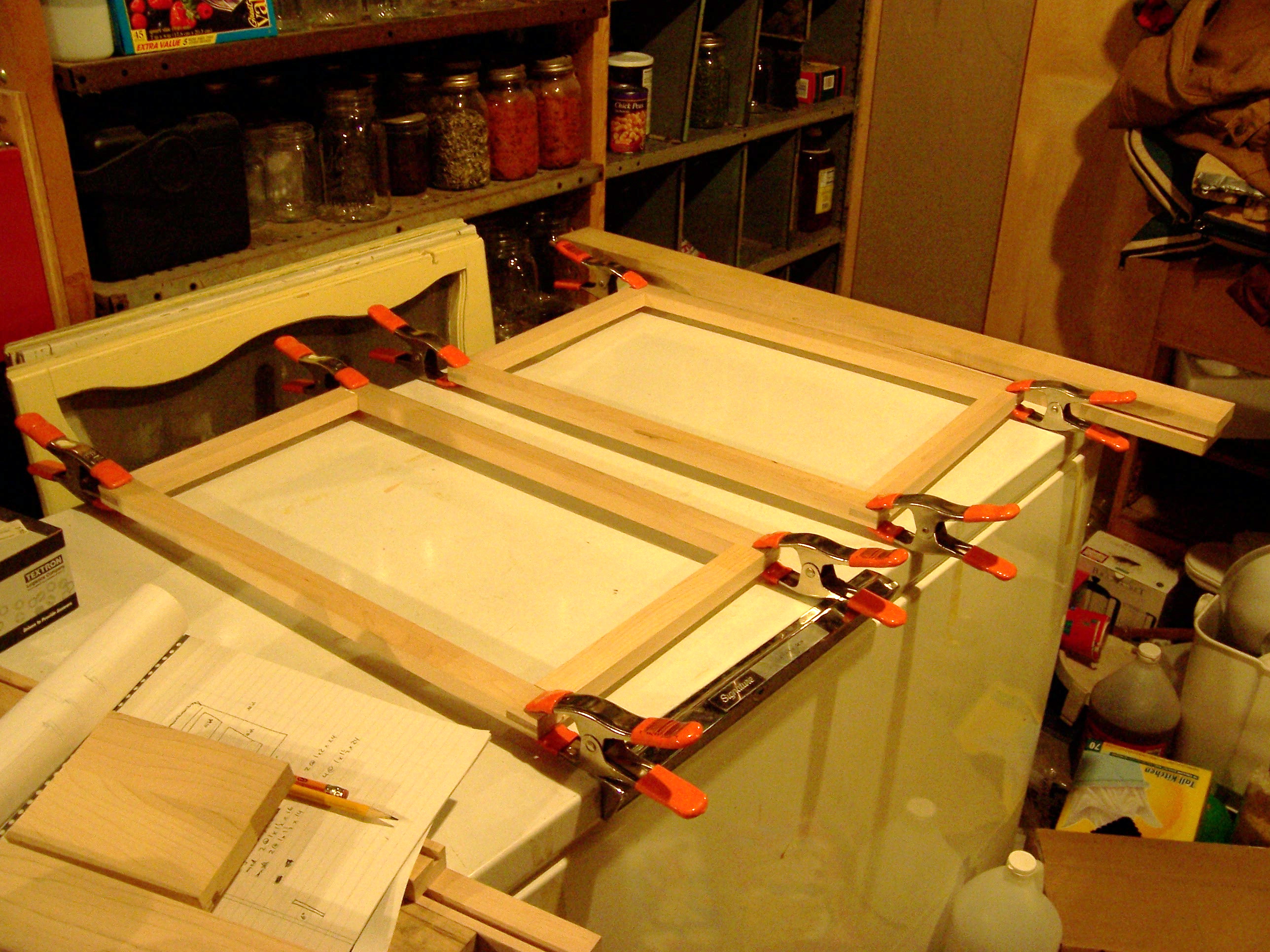
Building the Picture Frames

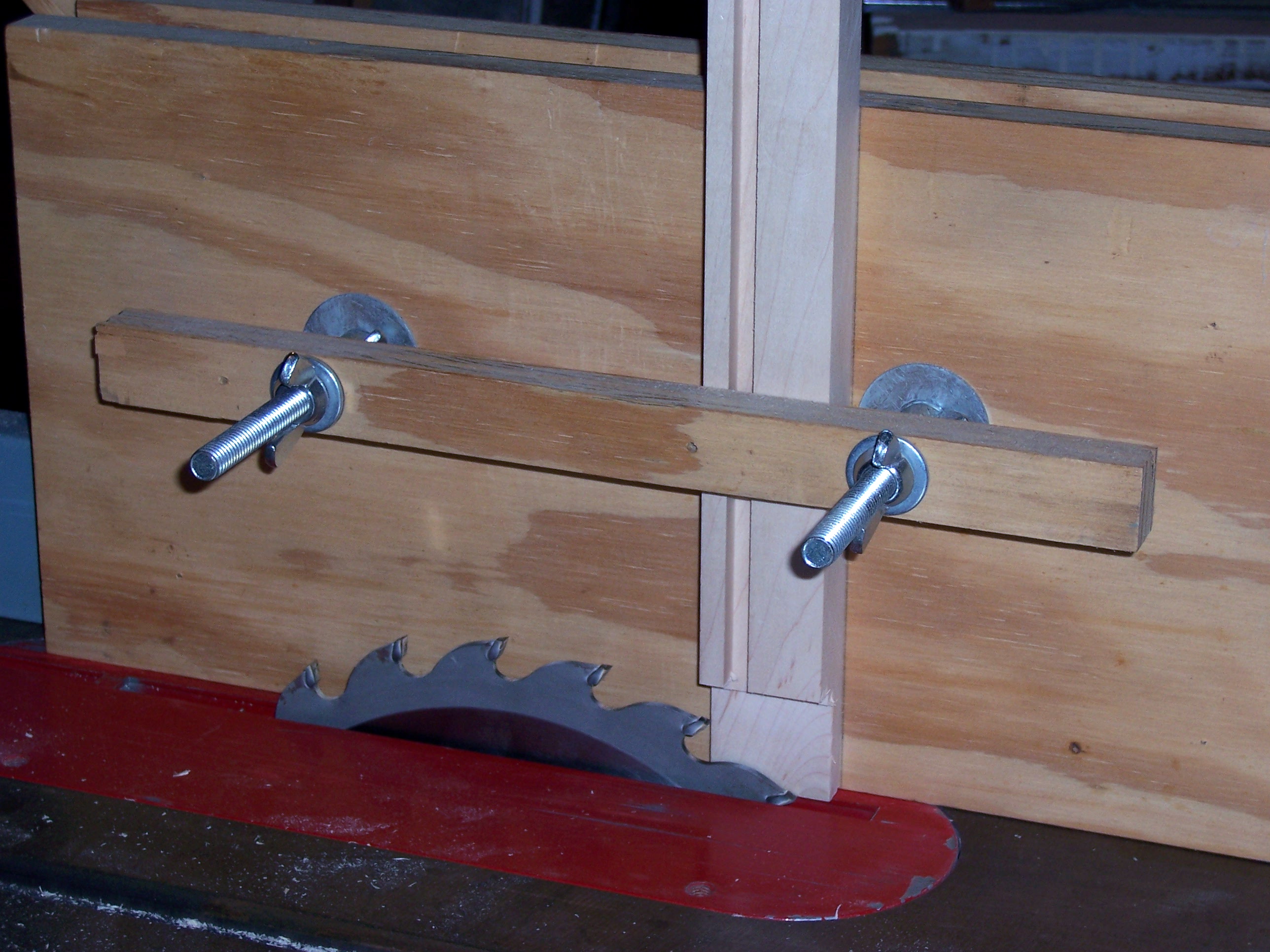
The front of the cabinet will have three swinging “picture frames,” which I made from maple that I had lying around. I used through mortise and tenon joints on the corners for strength, and cut them on a friend’s tablesaw using his tenoning jig.

Tenoning Jig

The joints fit pretty snugly, so they didn’t take much clamping during glue-up. (Love the random white-balance shifts my camera makes on indoor shots!)

Gluing up Picture Frames

Back to the Shop for the Rest of the Cabinet

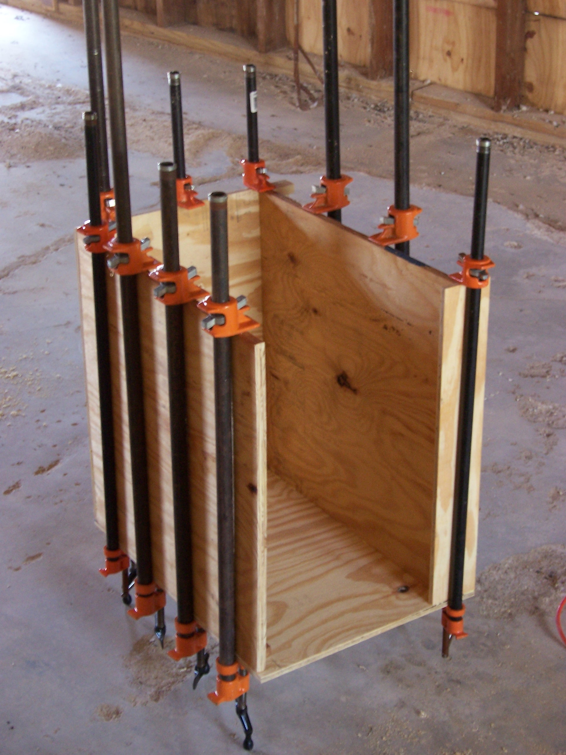
Because the cabinet’s side panels are continuous from top to bottom (they’re on the outside, not interrupted by any horizontal elements), they had to be glued on last, so I had all the other parts of the base assembled before adding the sides. I wasn’t sure yet how smoothly the glue-up was going to go, so I did them one at a time. In order to seat the biscuits as well as possible, I ended up locating a clamp over each one. You can never have too many clamps.

Gluing up Cabinet Base

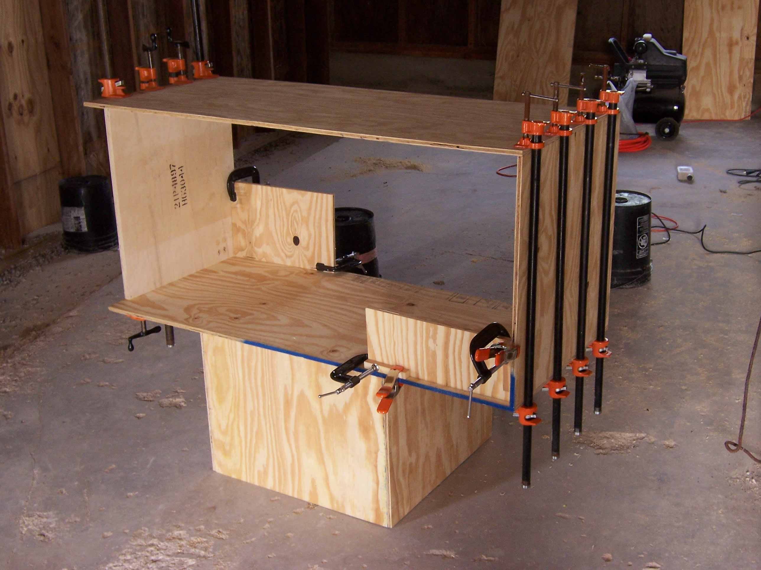
After completing the base, I glued up the outer frame of the upper cabinet. (It’s sitting on the assembled base.) Due to the design of the interior, I knew I was going to have to add the coffin panels last–and this meant that the outer frame would be unsupported whilst gluing it up. I clamped on a couple of pieces of scrap plywood to hold it square during assembly until dry. Once again, one pipe clamp over each biscuit.

Gluing Upper Cabinet Exterior

Because the upper cabinet is so large, I was really concerned about the integrity of its corners when I turned the outer frame upright–but I had nothing to worry about; it turned out to be surprisingly sturdy. I test-fit the panels for the coffin liner, then cut the liner fronts from more maple stock, using my tapering jig on a tablesaw. I left them a bit long so I could fit them exactly once I got them back to the cabinet–then regretted having done so, when I didn’t have a good way to cut them to size back at the shop.

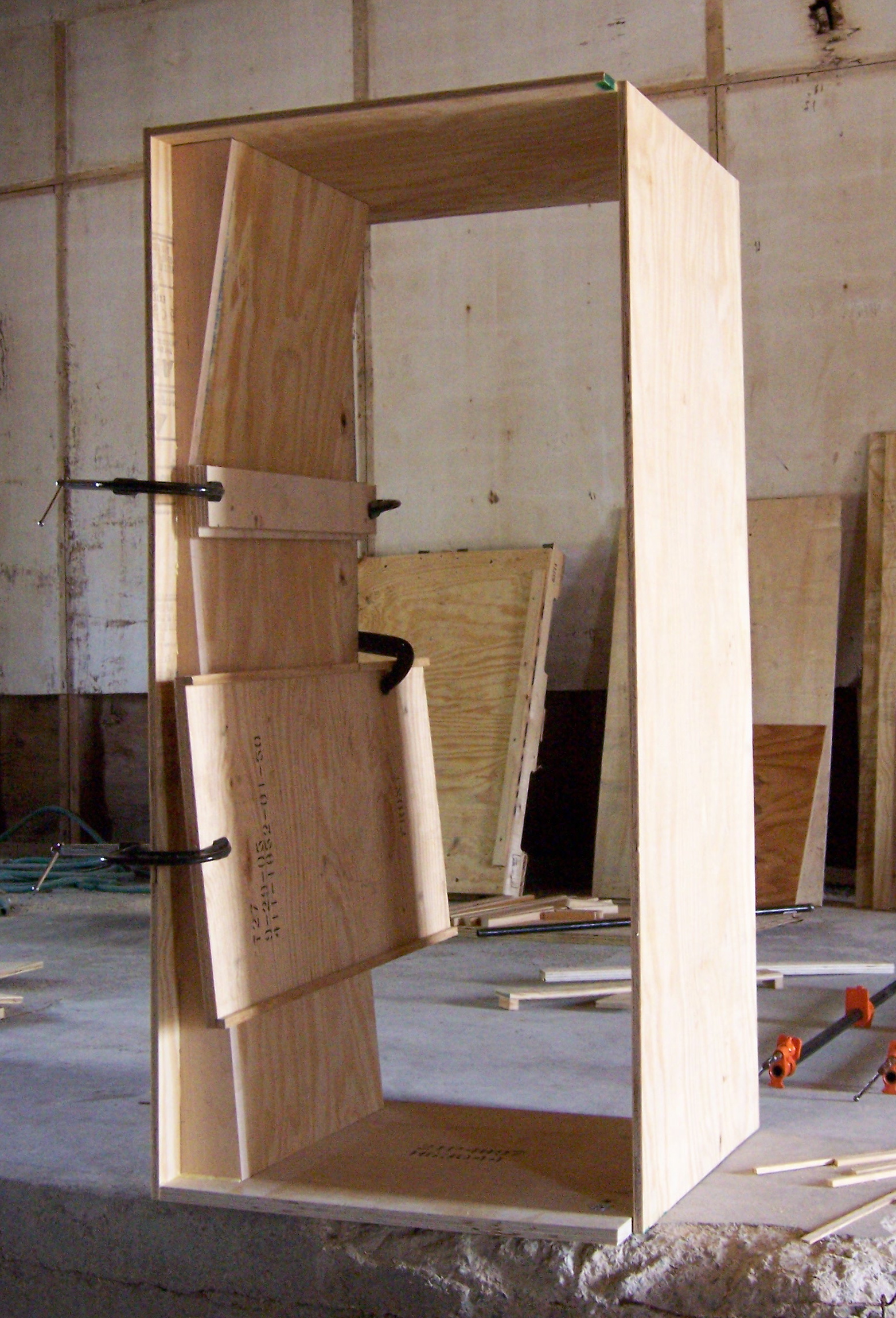
I biscuited the fronts onto the liners and let them dry, then fitted the entire assembly into the outer shell and biscuited the outer liner ends to the shell ends, the fronts to the shell edges, and the inner liner ends into the shell sides. I needed gravity’s help during assembly, so I built one liner at a time with the cabinet laying on edge, then turned it upright to clamp and dry. I used scrap stock to hold the inner liner ends tightly against the cabinet shell across their entire width.

Gluing Left Coffin Liner

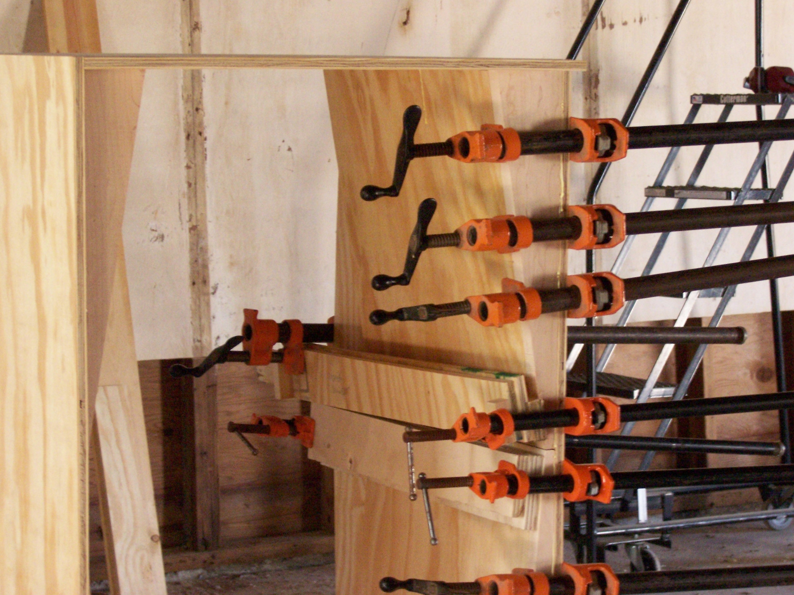
The biscuit joints on the right liner ended up a little more snug than those on the left, so I used a clamp per biscuit to pull them together. I would have used C-clamps for the entire face-to-shell joint, but I only have four 4″ clamps, so they’re all on the bottom section. The weight of all the pipe clamps sticking out the right side made the cabinet almost a little tipsy.

Gluing Right Coffin Liner

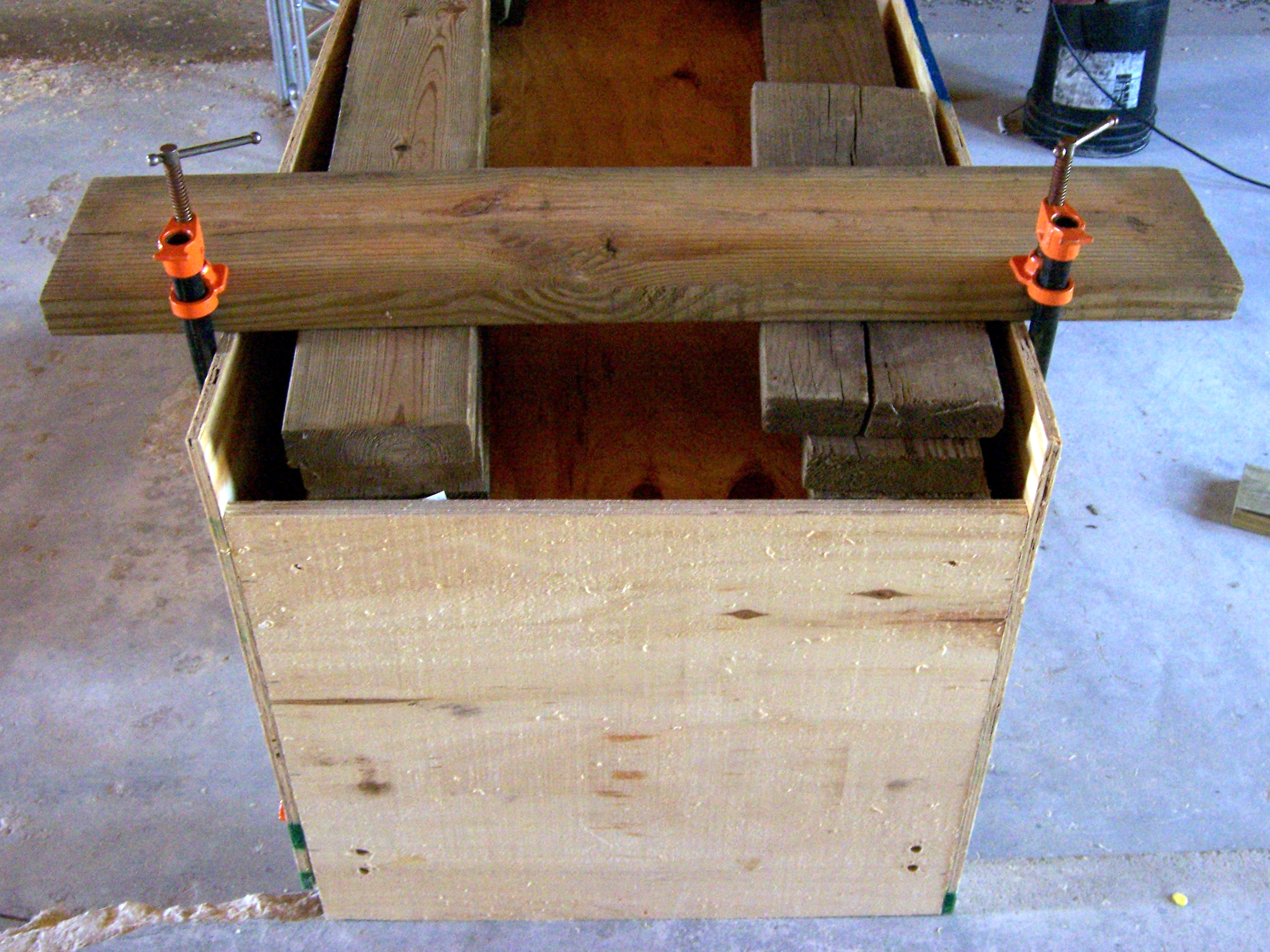
It’s not easy to see from this shot, but the coffin back is recessed a few inches into the cabinet, leaving a “service area” between the false back and the actual back door. That made it tricky to clamp the coffin back onto the coffin edges. I laid the whole cabinet upside down across a concrete ledge and a bucket (suspended to leave room on the bottom to attach clamps), stacked scrap 2x6es above the biscuits, laid a longer 2×6 across each end, and clamped that down tightly to the cabinet.

Gluing Coffin Back

I’m particular enough that I know I would have clamped it tightly like that anyway. However, in this case it was actually necessary–the coffin back was bowed about an inch and a half from end to end, so the top popped completely clear of its biscuits while clamping the bottom. Some of the biscuit joints were pretty loose, so I was really nervous it was going to spring open when I removed the clamps–but it held very nicely (thank goodness). If we do have any problems with it, I can always put some nails in from the back.

Finishing Touches

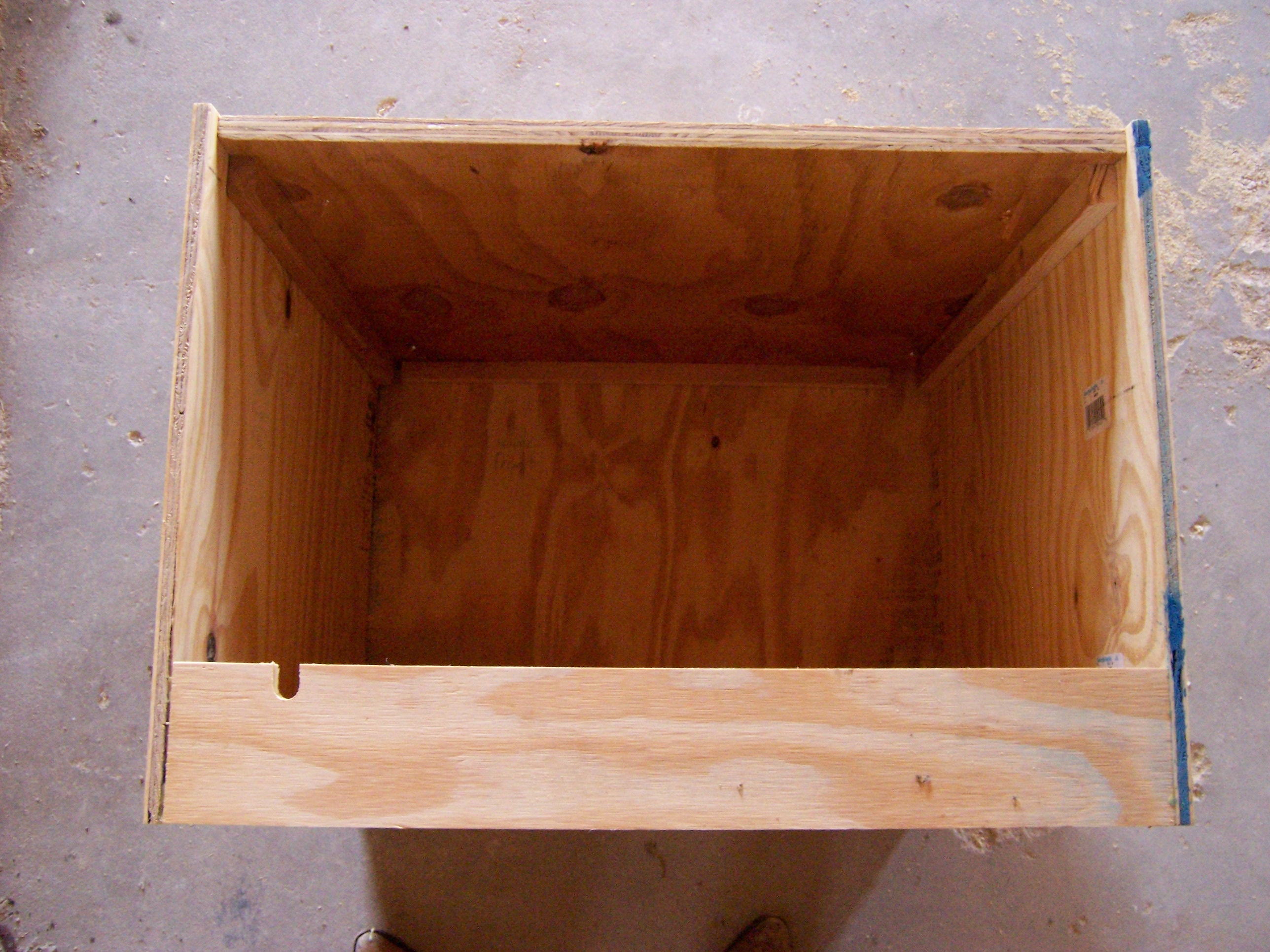
I needed a notch in the back of the base, for the power cord to come out when the back door is closed:

Base Notched for Power Cord

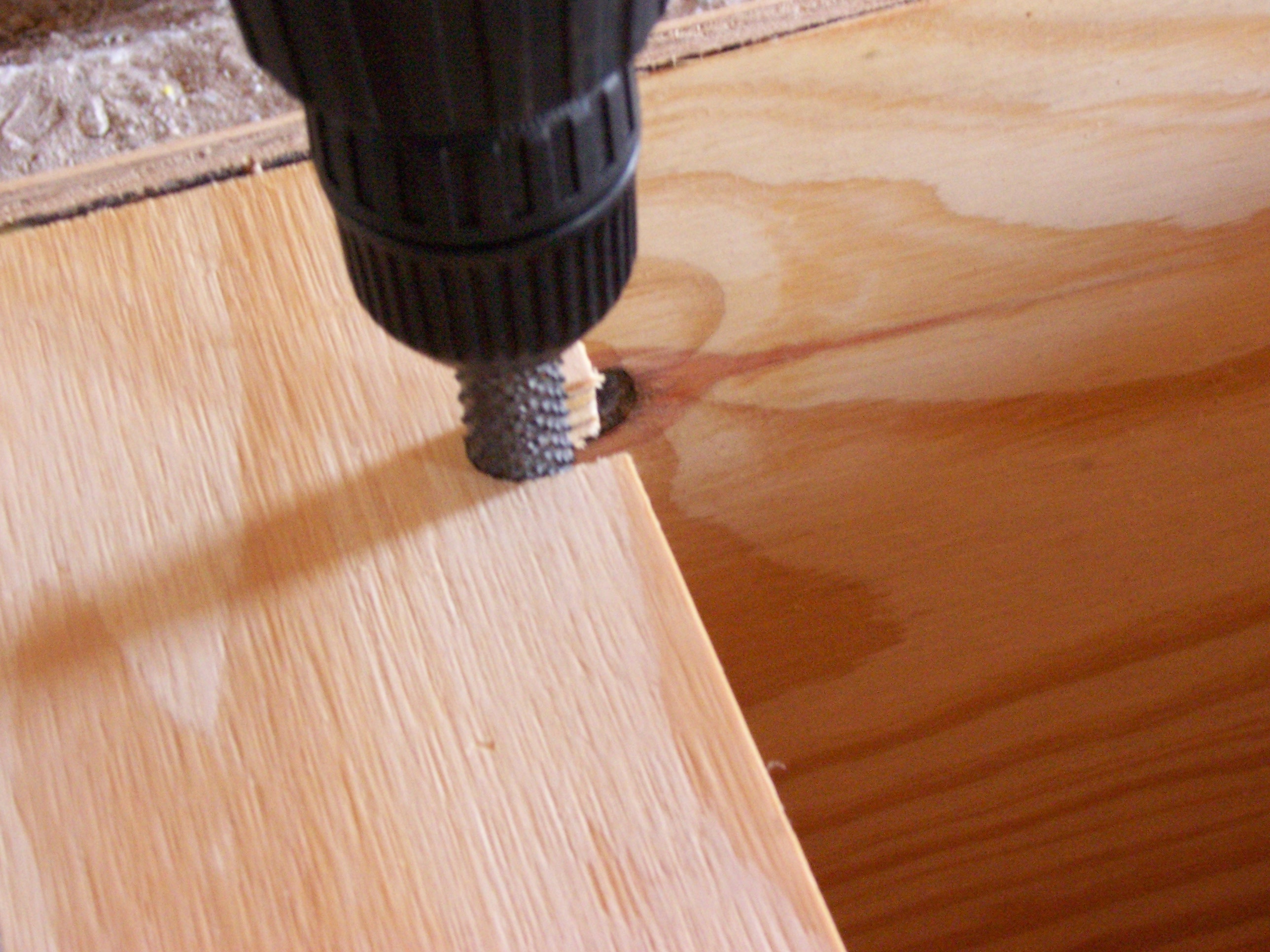
While the coffin back was drying (I gave it a long time, to be safe), I borrowed a rotary rasp and ground out the notch for the cord.

Notching Base with Rotary Rasp

Putty

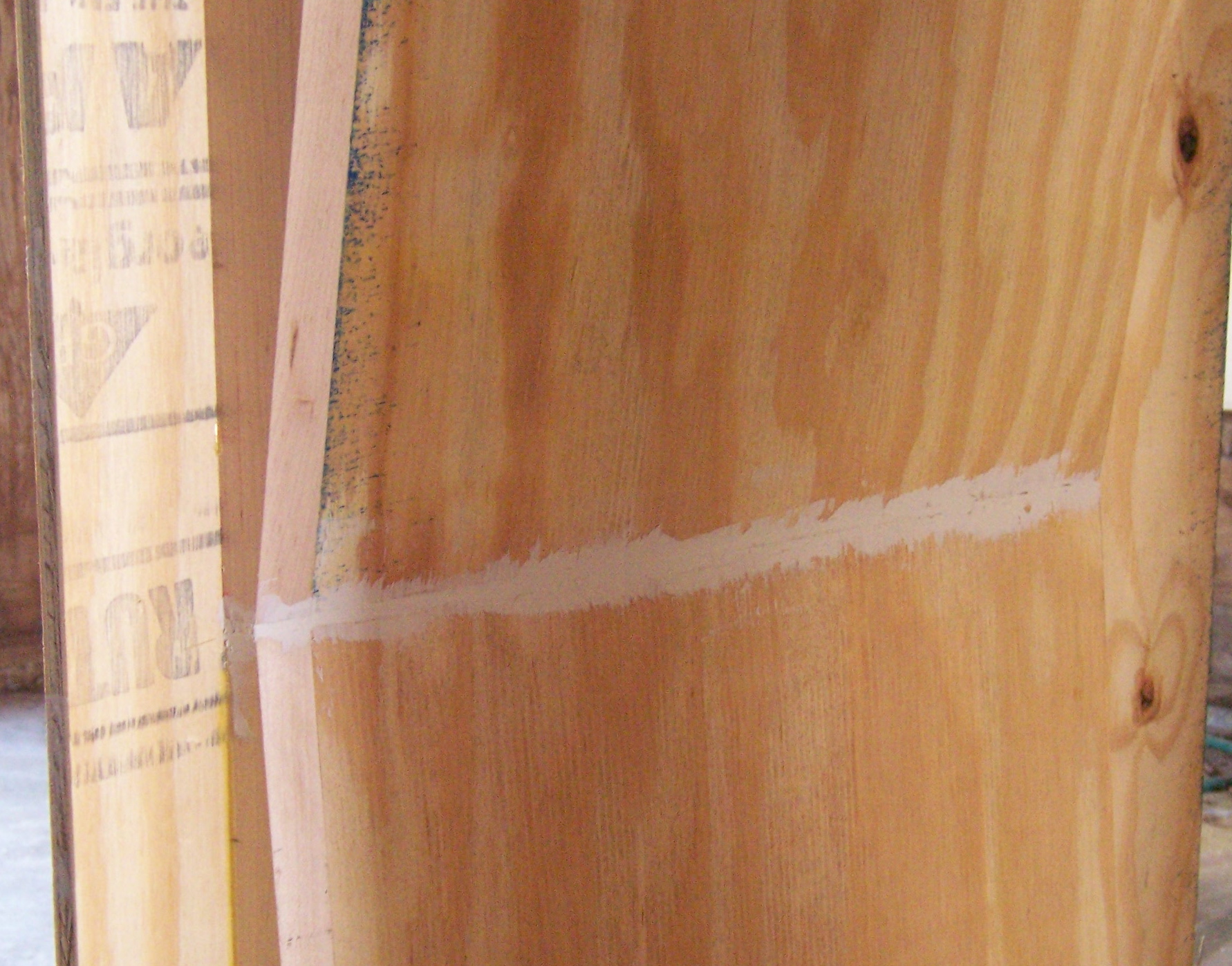
My cuts and joints weren’t perfect, and I had some cracks to fill. (They would have been better had I been able to use a tablesaw for the large pieces, but still not perfect.) I gooped them up pretty nicely with some painter’s putty and a putty knife, then did some final sanding to smooth up the plywood before priming.

Puttying Cracks

Primer

Because plywood just drinks up paint, I put two coats of oil-based primer on all of the visible (exterior) surfaces, and a single coat on all of the interior (back-side) surfaces to help seal against humidity changes. The primer said it dries to topcoat in only eight hours, and I was very impressed with how dry it was by this morning. I haven’t uploaded those pictures yet–they’ll come in the next post.

Cabinet Modeling

April 4th, 2006 by Keith Neufeld

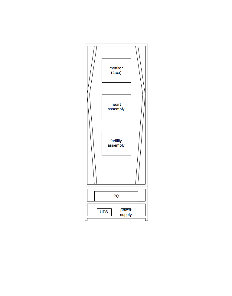
Andrea and I envision the cabinet for our TechArt final project, A Woman’s Mind, being built in two sections, for ease of hauling it around. The large, upper portion will contain the visible elements of the exhibit; and the small, lower portion will house the computer, UPS, LogoChip, cooling fans, etc.

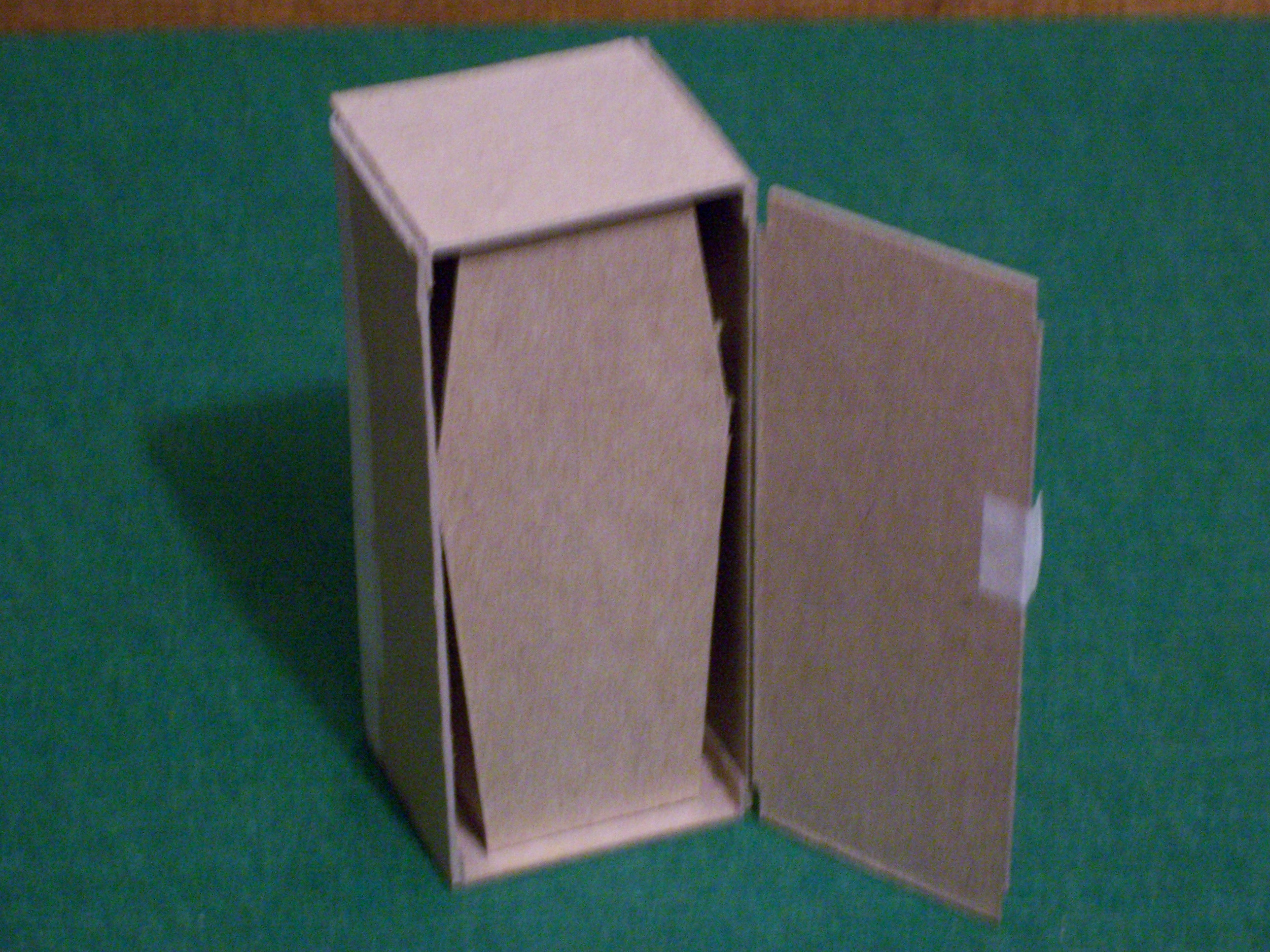
Tonight, I modeled the upper portion of the cabinet, to get a better feel for the proportions, and to have something more concrete to use when discussing construction details with Andrea. I used an amazing new CAD package called CardBoard (TM). Its user interface is incredibly intuitive; and in addition to the basics like Cut and Paste, it offers operations I’ve never seen in other CAD software, such as Slice, Fold, and Tape.

As you can see below, it has stunningly photorealistic, three-dimensional renderings, even going so far as to simulate shutter shake and mismatched white balance across multiple views.

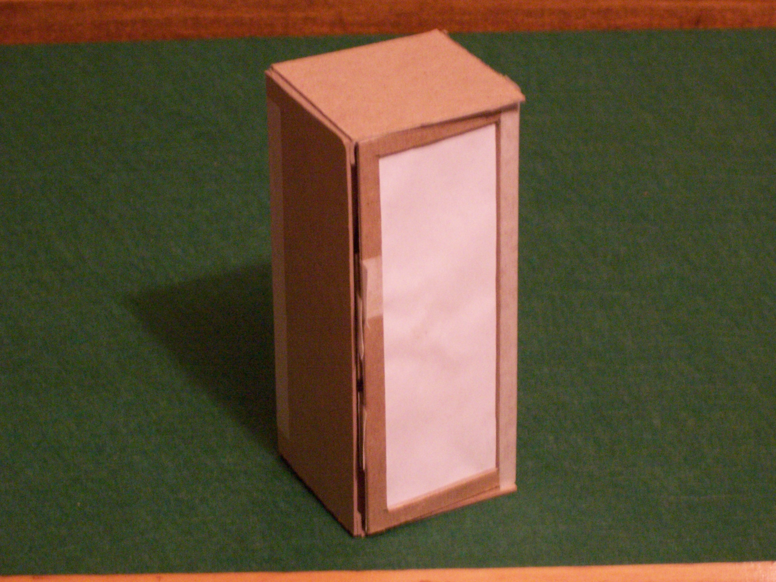
Here’s the upper portion of our cabinet with all of the screens closed. Note that the picture-frame of the outer screen is excessively wide; I hadn’t yet figured out how to model it at a narrower setting.

Cardboard Cabinet Model, Front View

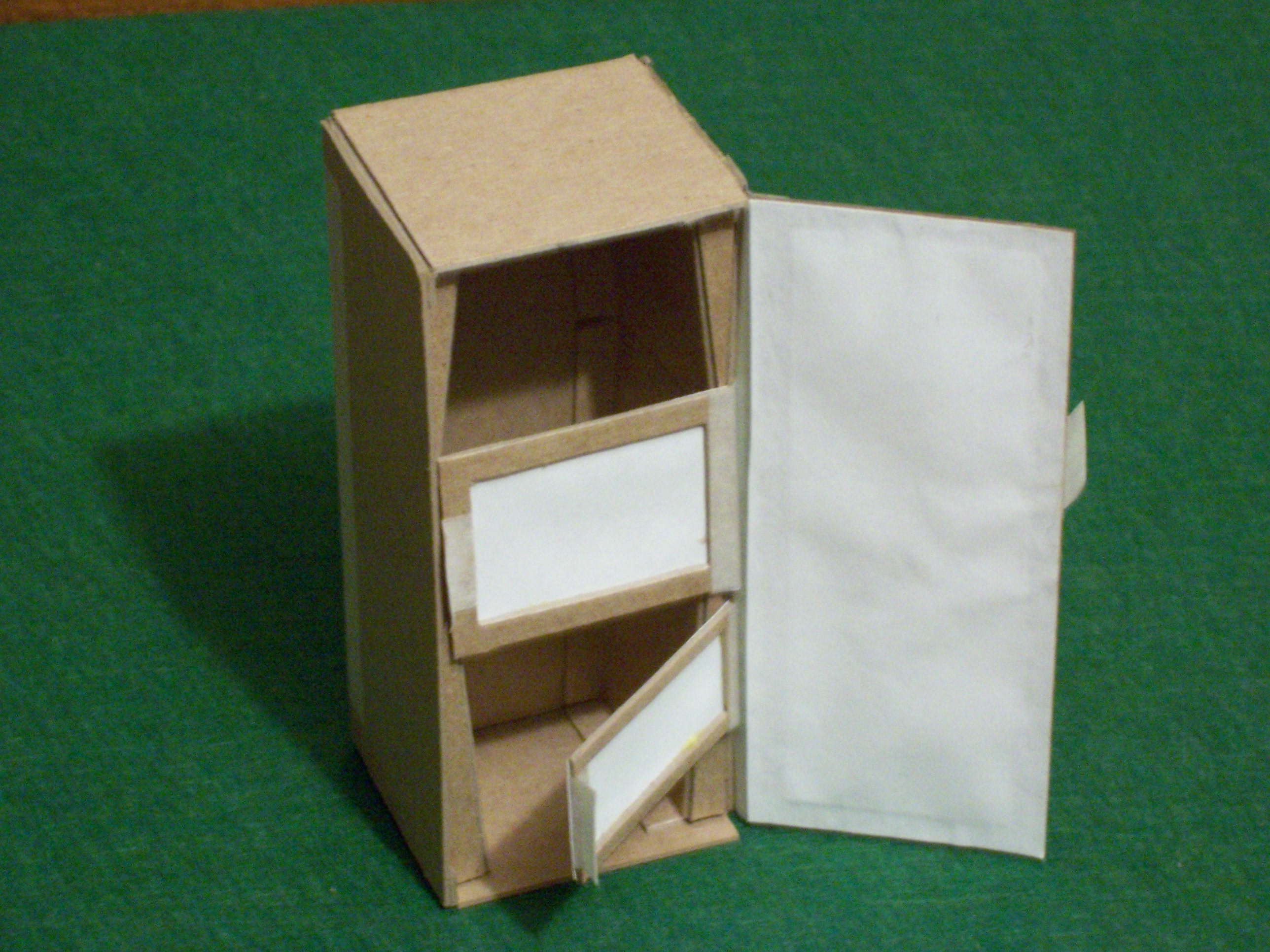
The outermost panel obscures the entire contents; opening it reveals smaller screens, and begins to expose the shape of the cabinet interior. Again, the picture-frame is a bit wide and not necessarily to scale.

Cardboard Cabinet Model, Front Panel Open

Opening all of the front panels reveals the entire shape of the cabinet interior; as well as the head (monitor), heart, and fertility mechanisms (not yet modeled).

Cardboard Cabinet Model, All Panels Open

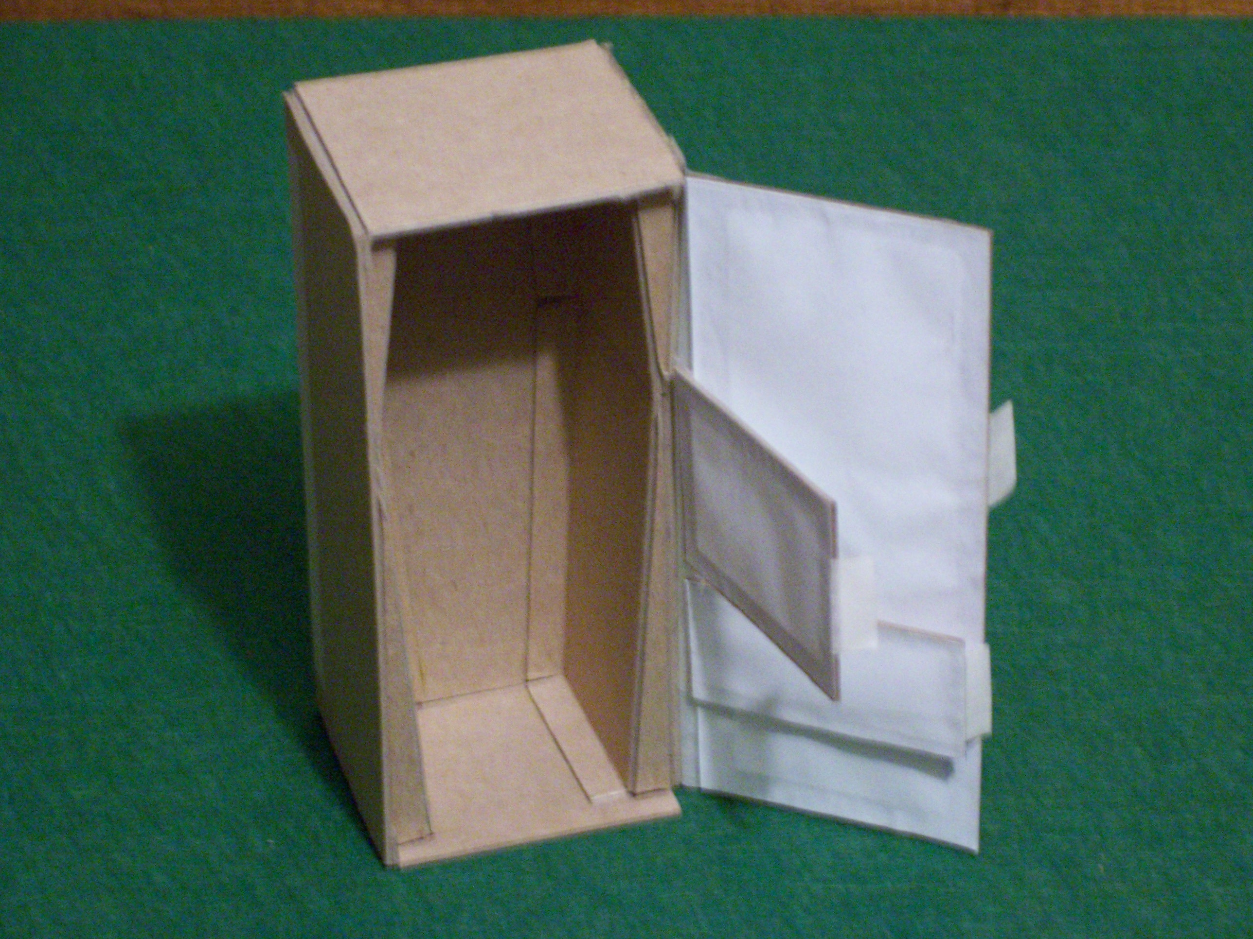
The rear panel will be locked and will open only for maintenance, providing access to a shallow false back and to the space surrounding the false interior. These spaces will hold the wiring needed to connect the sensors and actuators to the LogoChip, as well as the cables from the computer to the head monitor.

Cardboard Cabinet Model, Back Open

I plan to model the lower portion tomorrow night, working from the outline drawing of my earlier post. Hopefully Andrea and I can talk it over in class Thursday, and I can start actual construction this weekend.

Cabinet Plans: First Draft

April 3rd, 2006 by Keith Neufeld

First Draft of Cabinet Design

Multiplexing Ultrasonic Sensors

April 3rd, 2006 by Keith Neufeld

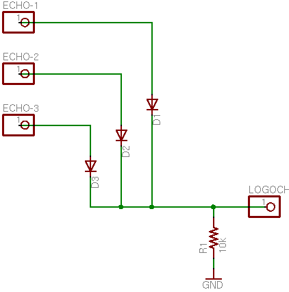
Last week in class, we talked about the potential need to have multiple Devantech SRF-05 ultrasonic sensors connected to one LogoChip. Different LogoChip output pins could connect to the different sensors’ trigger inputs, and then the sensors’ echo signals could all feed into one LogoChip input (because only one would be triggered at a time). We were trying to draw how to connect them together without burning them up, and I knew there was a right way to do it but couldn’t think of diodes.

Here it is:

Schematic to Multiplex Ultrasonic Sensors to One Digital Input

The echo signals are TTL, active high. That means that when the signal comes back, the sensor’s output will change from 0V to 5V. Put another way, 0V is normal; 5V means an echo was detected.

The diodes are one-way “valves” that allow electricity to flow from a sensor to the LogoChip when the sensor’s output is high (echo detected), but not from one sensor to another, under any circumstances. This protects the sensors from shorting each other out. When all of the sensors’ outputs are low, no electricity flows through the diodes to the LogoChip, so the pulldown resistor connects the LogoChip’s pin to ground (weakly) for a default input of low.

You could use some of Tom’s multiplexing techniques to connect even more ultrasonic sensors, but at $25 each, I expect cost will be the issue before running out of LogoChip pins.

Ultrasonic Rangefinder, Part II: Receiver

March 26th, 2006 by Keith Neufeld

Last night, I prototyped the transmitter circuit; today, I worked on the receiver. Coe’s design uses a two-stage op-amp circuit, with AC coupling on the input from the transducer to the first stage, to amplify the received signal before sending it to a comparator. I wanted to do the same, but I prefer to run from a single supply voltage, so I used an LM324 and added voltage dividers to bias the signal up to 2.5V.

First, I powered up the circuit from last night and measured the receiver’s signal on my scope. With the transmitter and receiver about 2” apart, the receiver signal was about 2V peak-to-peak, attenuating to about .5V p-p at 2’. If it continues to attenuate by a factor of 10 every 2’, then to measure distance out to 10’ (round trip of 20’), the received signal would be 2 * 10-10, or .2nV. Let’s hope that’s not the case!

The Circuit

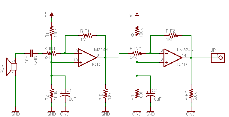
Each stage of the amplifier circuit is taken directly from the LM324 datasheet, “AC Coupled Inverting Amplifier” (although the two stages are DC coupled). The receiver’s signal is AC-coupled to the first amplifier’s inverting input, with a 2.5V bias to the non-inverting input.

Ultrasonic Receiver Amplification Schematic

I’m not sure why C1 is needed on the bias voltage divider, but the output waveform was considerably cleaner with it than without, so I left it in. I also don’t know what RB does, and Forrest Mims’ Engineer’s Mini Notebook on op-amp circuits didn’t show it but the datasheet did, so I left it in as well.

Values

The bandwidth-gain product for the LM324 is 1MHz, so a 24kHz input means the maximum possible gain is about 41.7. The gain is set by the quotient of the feedback and input resistors, and it worked very naturally to select RF = 1MΩ and RIN = 24kΩ.

According to Mims, CIN should have a value of 1 / (2π flow RIN), where flow is the lowest frequency to pass the filter. This gives CIN = 1 / (2π 24kHz 24kΩ) ≅ 280pF–except the first time around, I mistakenly calculated using RF (1MΩ) instead of RIN (24kΩ), and got 6.6pF. I had a 10pF on hand, so I substituted it; but it was still far too low a value, as will be seen shortly.

I breadboarded the circuit on my workbench and measured about .04V peak-to-peak directly from the receiver element, with both transducers pointed at the ceiling. (That was about an 8’ round trip, so my dire prediction of .2nV was fortunately not the case.) Next, I measured only about .08V p-p at the output of the first amplifier stage, so obviously something was wrong. It was at this point that I added C1, which brought the amplifier output to about .1V and cleaned it up dramatically–but with a gain of 40, it should have been more like 1.6V.

I was suspicious about the value of the AC coupling capacitor, CIN, and began substituting different values for it, with the following results:

Condition Signal Amplitude
direct transducer output .04V
CIN = 10pF, C1 absent .08V
CIN = 10pF, C1 = 10uF .1V
CIN = 100pF .5V
CIN = 1nF .6V
CIN = 10nF .6V

It looked like I must have miscalculated by an order of magnitude (at this point, I hadn’t yet caught my frequency error in the calculation), and 100pF was probably close to the best valued, but still a little too far down the knee of the filter’s response curve. .6V output was still a little low for a gain of 40, but within a range I was willing to accept, given that I was estimating the values by counting hashmarks touched by a dirty, wiggling waveform on my scope. I put the 1nF back in and called it good.

Second Stage

After honing the values on the first stage of amplification, the second stage was easy–just more of the same. I used all the same values, but omitted the AC coupling capacitor, since I’m happy to DC-amplify around the 2.5V bias. The second stage gives me a trapezoidal waveform (clipping both the top and bottom of the transducer’s sine wave) running rail-to-rail of the LM324′s advertised output capacity–from 0V to about 4V. Tomorrow I need to run that through a comparator to clean it up just a little more, and then steal John’s capture/compare LogoChip code to start timing the echoes.

DIY Ultrasonic Rangefinder

March 25th, 2006 by Keith Neufeld

Ultrasonic rangefinders detect objects and measure distance the same way as a bat: Emit a high-pitched “ping” and measure how long it takes the echo to return. The speed of sound in air is nearly constant (ignoring slight variations due to air pressure and humidity), so the time from ping to echo translates directly into the distance to the object.

I’m interested in ultrasonic rangefinders for both hobby robotics and our TechArt final project. They’re available commercially, but $25 each adds up pretty fast if you need multiples to establish a view all around a bot or across the wide front of an art installation. All Electronics has transducer elements for $1 each in quantities of 10 or more, so I ordered a batch of them in hopes of building a rangefinder myself. At $2 each (two transducers, for send and receive), I can add a fair bit of supporting circuitry before hitting the $25 mark.

The Plan

I’m basing my circuit on a design by Gerald Coe at http://www.robot-electronics.co.uk/htm/srf1.shtml, and adapting it for different design goals. His circuit uses a dedicated PIC to provide the oscillator, a MAX232 to generate 16V to drive the transmitter, and 40kHz transducers. For now, I want to run my rangefinder from an existing LogoChip that’s also doing other work, avoid the complexities the MAX232 adds, and use transducers with a different nominal frequency. Later, I might build separate modules intended to stand alone and run with very low power.

Initial Testing

According to a comment on the All Electronics page for the transducers I ordered, they run at 24kHz. The first order of business was confirming that operating frequency.

I hooked my function generator to my frequency counter and scope and dialed in 24kHz, to make sure I was in the neighborhood before connecting the transducer. I then connected one transducer to the function generator to serve as the transmitter (with the frequency counter still attached), and the other transducer to the scope to serve as the receiver.

When I pointed the transmitter at the receiver, a signal showed up on the scope; when I pointed it away, the signal abated. I could bounce it off my hand and receive it, but not off the ceiling. (I’m guessing the elements weren’t aimed well enough and/or the amplitude wasn’t high enough.) And changing the oscillator frequency confirmed that 24kHz is indeed optimal.

So the project is at least possible. That’s a good start!

Connecting the LogoChip

I really didn’t feel like disassembling my balance-bot project, so I’m sure glad I bought several PICs! I built up a breadboard with another LogoChip on it and verified operation. Then I took my motor-control PWM code and cleaned it up to generate a single frequency signal.

Testing with my frequency counter and scope hooked up, it looks like I need timer 2 with a prescalar of 1 and a period of 82 to get as close as possible to 24kHz. Hm, 82 * 24k ≅ 2M, which tells me that I really don’t understand what timer 2 is using for an input clock. Wait–yes, I got it. The PIC has an internal 4x increase in oscillator speed, so the 2Mhz timer oscillator leads to the 10Mhz clocking.

Driving the Transmitter

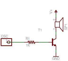
I first tried powering the transmitter element with an NPN driver, for simplicity and to allow experimentation with the drive voltage:

Ultrasonic Transducer Driver using NPN Transistor

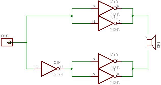
I connected the receiver element to my scope to detect the signal, and was surprised to detect nothing. I looked back at Coe’s schematic and noticed that he drives his transmitter in a push-pull arrangement using the MAX232, so I scrounged around for something with totem-pole outputs that I could use to test. The quickest thing I could come up with was a 7404:

Ultrasonic Transducer Driver using LS7404

And this time, I did show a received signal on the scope, albeit a slightly weak one; so I guess the push-pull drive is necessary.

I’m not satisfied being restricted to a 5V drive, because Coe specifically mentions using 16V to get adequate detection at greater range. However, I’m not sure I have anything on hand that will do exactly the right job and which I’m happy using. None of the options quite work out:

  • The 74xx chips with “high-power output” and 754xx peripheral drivers run open-collector, and I don’t see a good way to use that to provide push-pull.
  • The 754410 H-bridge driver adds about $2 to the cost–not bad, but I’d rather avoid it if I could.
  • The MAX232 adds about $1 plus numerous supporting components–and Coe mentioned that it generates enough noise that he shut it down after each ping to keep it from interfering with the echo detection circuitry.

I’ll probably prototype with the 754410 since I have some on hand, and keep looking for other options.

Robot Throwdown!

March 23rd, 2006 by Keith Neufeld

I was joking around with a coworker asking how soon he was going to switch a Unix server to use LDAP for login authentication instead of the local password file, and after seeing my two-wheeled balance ‘bot crash and dive yesterday, he replied:

When a two-wheeled balancing robot scoots into my office and tells me to do so!

Then after I asked whether he was willing to commit to that promise, he backpedaled and followed up with:

I sense trickery, either that or motivation to expidite the process.

Just in case I better clarify, lest some off-the-wall intrepretation of the rules takes place.

I, Garrett Marks, will enable LDAP authentication on zion for system accounts when,

A two wheeled, self powered, balancing robot enters my office under its own power (the door may be held open for the poor fella) and audibly asks me to “enable ldap authentication on Zion, please” via some sort of electronic powered sound producing system (no it can’t just hand me a post-it note). The robot must be assembled by Keith Neufeld.

And later, another caveat:

A1: The robot must be standing upright when it delivers its request.

Okay, Garrett; you’re on!

Edge-Lit Scratched-Character Displays

March 21st, 2006 by Keith Neufeld

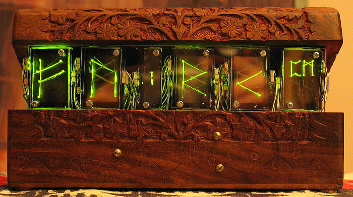
Ted Johnson's Edge-Lit Clock

Okay, I’m not much for filling blogs with links to blogs that link to other blogs ad infinitum . . . but this is just too cool. Ted Johnson built a clock out of acrylic sheets with runes scratched into them, edge-lit with LEDs, and stacked to show multiple different characters per position.

Ted Johnson’s Project

EAGLE for Circuit Design and PCB Layout

March 21st, 2006 by Keith Neufeld

I’ve been looking for circuit design and PCB layout software for a long time, and in the past couple of weeks I’ve settled on EAGLE. I’ve used it to draw up the most recent schematics here on my blog. Its key advantages for me are:

  • There’s a freeware version. I don’t do enough circuit design to justify paying a lot of money for commercial software–especially software that I haven’t got to try first.
  • It can output netlists from it circuit design module to use with other PCB layout software, and it can output Excellon drill files to use on my friend Joel’s CNC drilling machine.
  • It runs on Windows, Mac, and Linux–and I expect to use all three versions regularly.

To understand why I like it so much, though, it’s worth running through the other software I’ve used.

Electronics Workbench: Multisim and Ultiboard

I got a student copy of Multisim and Ultiboard with my electronics textbooks in 2004. I used it a lot in class, and I think it’s fantastic for doing circuit simulation. It blows me away that it’s even possible to do that level of analysis and simulation on a commodity PC, and I really appreciate Multisim for what it does.

Unfortunately, I also had a not insubstantial list of complaints:

  • The Multisim (circuit design/analysis) UI is pretty glitchy. I had a lot of trouble selecting the component I wanted to move; I’d box-select a group of components and drag them, and parts would get left behind (and disconnected); etc.
  • I had trouble getting the hang of the UI for Ultiboard, the board layout software. I don’t remember exactly what I didn’t like, but I know I gave up in frustration pretty quickly.
  • Worst, though, is that the installation uses a nodelocked license. I installed the software on two PCs in Pittsburg, and when I left, I completely uninstalled it. I’m now within the rights of my license to install it on another PC–but I’ll have to call EWB to get another install code, because I’ve installed it too many times to get a new code automatically.
    So I feel like the next time I install it, I need to be ready to put it onto one PC where I’m going to leave it forever–because how many more times can I call them and tell them (truthfully, but they have no way of knowing that) that I’m moving it to yet a different PC? The offshoot of that is that I’ll probably never install it again.

PCB123

I had used ExpressPCB (next) a long time ago, and while I was searching for it recently, accidentally installed PCB123 instead. Like ExpressPCB, PCB123 is a company that makes small quantities of PCBs for prototyping and hobbyist use, and gives away the software to design the circuit and layout the boards. I don’t even remember what I didn’t like about PCB123–I just know that it took me about five minutes to realize it wasn’t ExpressPCB and I wasn’t willing to learn to use it.

ExpressPCB

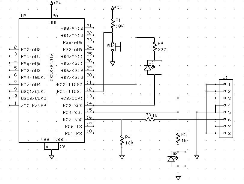
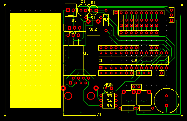
LogoChip in Altoids Tin Schematic
LogoChip in Altoids Tin Layout

I had been happy with ExpressPCB for a long time. They’re a board manufacturing house, and they figured out long ago that if they give away circuit design and board layout software, they’ll entice people to use their services.

I think they walk a delicate line trying to decide how much functionality and interoperability to put into their software–too much and people might use their software and then have boards manufactured elsewhere; too little and people will get frustrated using their tools.

In my case, despite finding their UI to be the absolute best I’ve handled, the functionality is too low, and I’ve moved away from their software. With a little more functionality, I’d still be using their software, and I’d turn straight to them when I need a board commercially produce.

First, I have to sing their praises:

  • I found the UI to be fantastic, in both the circuit design and board layout sections. The toughest operation for this type of software seems to be selecting an existing part to move, and I would almost always get exactly the part I was trying to select; it was easy to reselect a different part in the cases when I didn’t get it on the first try.
  • Their board layout software has a netlist checker, so you can see which pins need to be connected. (However, see “ratlines” below.)
  • The UI just has a good “feel” to it–everything handles very nicely.

However, its drawbacks were serious enough for me to move away from it:

  • Foremost, because the software exists entirely to get you to buy boards from ExpressPCB, it has no facility for exporting drill files. I’m drilling boards on my friend’s machine, drawing traces by hand, and etching in a plastic tank–I pose no threat to ExpressPCB’s business–but I can’t use their software to automate my homebrew process. It can’t be made to meet my needs.
  • ExpressPCB doesn’t prepopulate the PCB layout with the components used in the schematic. You have to add and label each component individually. That’s time-consuming and error-prone.
  • ExpressPCB doesn’t support ratlines indicating netlist connections. Yes, it can highlight solder pads that need to be connected–but it’s easier to lay out traces when you have ratlines indicating all of the connections that need to be made.
  • The board layout UI is a little over-eager to merge connections. I’ve had to scroll the entire board off the screen when calling up a new part to add, because with the board on the screen, the part got merged into existing traces before I could even select where the part was to be placed. Similarly, I’ve had entirely unrelated traces merged together because I was dragging a set of parts to a different area of the board, and corners of traces I was dragging (and would have rerouted as the next step) landed on top of other traces.

The biggest issue, of course, was being able to produce the interchange formats I needed–but the other issues served as cautions while looking at other packages.

FreePCB

FreePCB is a really nice-looking package, an amazing programming accomplishment from a single individual, and free of cost but not open source. I like it a lot, and I expect to use it for larger boards in the future. It’ll import component and netlists from other software, and it’s what led me to EAGLE for circuit design.

A few observations:

  • It doesn’t have any corresponding circuit design software. That’s means there’s no way to automate back-annotation when changing a design during PCB layout, and the coupling for forward updates isn’t as tight as with some of the other packages.
  • It’s extremely tedious to lay out a board from scratch without an accompanying parts list from a circuit design package. FreePCB is intended to be used in conjunction with circuit design software, and I’d want to use it that way most of the time. However, I was trying to lay out a one-component, two-connector board without having drawn the schematic, and found it prohibitively difficult to do.
  • It has ratlines, a nice feel, decent export capabilities, etc. It was designed by an engineer–it was made to work well.

EAGLE is a little smoother for me to use, but the free version has some restrictions that I may eventually run into. When I do, I plan to use FreePCB for those boards.

Hand-Created Drill Files

For a 2″ x 2.5″ board with a PIC microcontroller, RJ-45 connector, LED array, lots of sockets, and supporting passives; for the one-component board I mentioned above; and for a couple of other boards I’ve worked on since then; I’ve drawn the circuit (and sometimes the PCB) in one package or another, and then laid out the drill file by hand. It’s not hard–key in a zillion (x,y) coordinates, plot the file in gnuplot to make sure it looks right, use a small Perl script to translate to rudimentary Excellon code, and drill it.

It’s a dumb way to have to do things, but it got me a drill file that I couldn’t get out of ExpressPCB, and it got me a layout that I didn’t have time to figure out how to do in FreePCB. I’d rather not make a lifestyle of it, though.

EAGLE

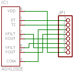
ADXL202E Carrier Board Schematic
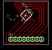
ADXL202E Carrier Board Layout

Which brings me to EAGLE, the software I think I’m going to be using for a long time to come. It outputs the formats I need, it runs on all the OS platforms I use, and a slightly restricted version is available at no cost. The freeware limitations won’t impact me for quite a while: only one-sheet schematics, only two-layer PCBs, and PCBs no larger than 4″ x 3.2″. I’ll hit the last one first, and I’ll use FreePCB for layout when it happens.

I do have a few complaints about the UI:

  • It’s often very difficult to select an onscreen part to move to a different location. I’m starting to resort to drawing a select box around the interior of the part in order to select it and nothing else; I much prefer the click-click-click to cycle through overlapping parts. I think there’s a right-mouse trick to cycle in EAGLE, and I need to learn it.
  • Speaking of right-mouse, too much of EAGLE’s functionality depends on it. I use the right mouse button nonstop when I have one, but my PowerBook doesn’t.
  • The screen doesn’t automatically refresh objects when other objects have been covering them and are removed, at least not in the X11 versions. Yes, I can hit F2 to redraw the screen, but it’s often really messed up until then.
  • EAGLE seems to have serious problems performing unintended merges during component rotation operations–I have PCB traces that get stuck together and I have to reroute by hand. Worse, that situation seems to corrupt the netlist, because it changes the ratlines. I’m stuck with leftover ratlines that disagree with their traces, and no way to correct them. This is very problematic.

But mostly gratitude at finally finding software that does so many things right:

  • Pretty good coupling between the schematic and board layout sections, including prepopulating components and ratlines
  • The ability to export a netlist to use in a separate board layout program
  • The ability to export drill files in Excellon format to drill my own holes

LogoChip and PWM: Bidirectional Motor Speed Control

March 21st, 2006 by Keith Neufeld

Early last week, I was working on expanding my PWM motor speed control to be able to reverse directions. I had the PWM output from my LogoChip’s PWM subsystem, and I wanted to add another line to indicate whether to spin the motor forward or backward.

Because I’m using the 754410 motor driver chip, I need to apply the PWM signal to the pin corresponding to the direction I want the motor to turn, and keep the other 754410 input pin grounded. That means I needed to translate from (speed, direction) to (move forward, move backward). I have lots of digital logic chips lying around, so I knew I could put something together.

Ideal Schematic

Ideally, if I had all the gates I wanted on a single chip, it’s this simple:

Ideal Motor Direction Control Schematic

(Pardon the truncated labels on the right side–EAGLE did that for me in the PNG export.)

I’m using a direction of 1 to mean forward and 0 reverse. So here’s what the schematic means:

  • If the PWM speed signal is on and Direction is 1 (forward), activate the Forward output.
  • If the PWM speed signal is on and Direction is 0 (reverse), activate the Reverse output.

I could have done this with a 74*08 quad AND gate and a 74*04 hex inverter, but that’s two chips. It offends my sensibilities to use two chips when one would suffice, plus I don’t have a lot of room to spare on my LogoChip breadboard. So I looked for something better.

74LS138

I was looking for a chip with a data input and address input(s) to select which output line the data was routed to, and the closest I could find was the 74*138. The ’138 is 3-to-8 decoder/demultiplexer, meant to decode three lines of an address bus into eight enable inputs for memory or other chips: You supply a three-bit address to its inputs, and it activates the corresponding one of its eight outputs.

This wasn’t exactly what I needed, but there’s a trick I figured I could use. I applied the Direction signal to an address input, to select which output would receive the PWM signal; then I applied the PWM signal to one of the enable inputs. In theory, that means that both outputs would be inactive any time the PWM speed signal was off, and the appropriate output would be active when the PWM speed signal was on.

Motor Direction Control with 74LS138

Unfortunately, EAGLE’s circuit symbol for the ’138 is a block diagram that doesn’t illustrate the internal logic, but here’s what’s going on. Direction is applied to address line A, which will select output Y1 (Forward) when Direction is 1 (forward) and output Y0 (Reverse) when direction is 0 (reverse). And the PWM speed signal is applied to active-high enable line G0, to activate the appropriate output whenever it’s high. The other enable lines are active-low, so they’re tied to ground to be active all the time.

But you’ve probably noticed that it’s still a two-chip design–there are two inverters off to the right. Unfortunately for this project, the ’138′s outputs are active-low. Most memory chips have active-low enable inputs (it makes it easier to gang together open-collector selection circuitry), so naturally the ’138 provides an active-low output. In order to get the active-high signals that I wanted to feed into the 754410 motor driver chip, I had to invert the ’138′s outputs, and that meant adding another chip. I did build and test this circuit as a proof of concept, but I still wasn’t satisfied, and kept looking.

As a bit of an aside–I could have used active-low signalling to drive the 754410. It’s an H-bridge driver chip, so it powers the motor whenever it has different inputs. When the inputs are the same–low or high–the motor doesn’t run. However, I’m guessing there’s slightly more power consumption when both inputs/outputs are high, and I wanted it to draw as little power as possible in the quiescent state, so I was determined to come up with a circuit that would provide active-high signalling.

One other note–I tied both inputs to ground with pull-down resistors. As long as the LogoChip is providing outputs, these are irrelevant–but when the LogoChip first powers up, its ports are configured as inputs and don’t provide a valid TTL signal to the ’138. The motor was freaking out (that’s the technical term) when I’d reset the LogoChip, so I added the pull-downs for power-up sanity.

74LS153

The 74LS153 is my final, one-chip solution. It’s a dual 4-line to 1-line data selector/multiplexer, meant to do exactly, uh, the opposite of what I need: It picks which of four inputs to send to the output. But that’s okay–there are two selector/multiplexers in one package. That means I can use one multiplexer to select whether the PWM or nothing goes to the Forward output, and the other to select whether nothing or the PWM goes to the Reverse output. Looks a little somethin’ like this:

Motor Direction Control with 74LS153

Again, EAGLE renders the ’153 as a block without exposing its inner workings, so explanation is in order. Inputs A and B are the address lines (think A0 and A1) to select which data input will be delivered to the output. Note that A and B select for both multiplexers at the same time, so I don’t have to wire to separate address lines for the two multiplexers. Input B (address line 1) is tied to ground because I always want it 0–I’m only working with the first two possible inputs. And the active-low enable inputs are tied to ground, because I always want the chip enabled.

The first selector has the PWM signal at its 0 input (1C0), ground at its 1 input (1C1), and its output (1Y) feeding the Reverse driver. So when Direction is 0 (reverse), the first selector will pick input 0 (PWM) and feed it to the Reverse input of the motor driver. When Direction is 1 (forward), the first selector will pick input 1 (ground, or nothing) and feed it to the Reverse input of the motor driver.

Likewise, the second selector has ground at its 0 input (2C0), the PWM speed signal at its 1 input (2C1), and its output (2Y) feeding the Forward driver. When Direction is 1 (forward), the second selector routes input 1 (PWM) to the Forward motor drive pin. When Direction is 0 (reverse), the second selector routes input 0 (ground) to the Forward motor drive pin.

Because human minds are forward-centric (there’s a very interesting section of linguistics that studies which word out of pairs of opposites has connotations of dominance: forward/reverse, up/down, hot/cold, etc.), it would seem to make more sense to use the first selector for the forward drive and the second selector for reverse. But I wanted Direction == 0 to activate the first selector and Direction == 1 to activate the second, and because I made Direction == 1 for forward, it worked out like this.

I added pull-down resistors again–different values this time, based on the datasheet and application notes. And the circuit works, in a single chip! Yeah, the ’153 is overkill for this application–but I can’t find a simpler single chip that’ll do the job. I could do it with a PAL and have room left over for other tasks; but in the absence of a need for other logic in this project, that’s even more overkill.

Finis.