Archive for the ‘Hacks’ Category

DIY Power Injector for Axis 2100 Network Camera, Part I: Investigation

Tuesday, March 24th, 2009

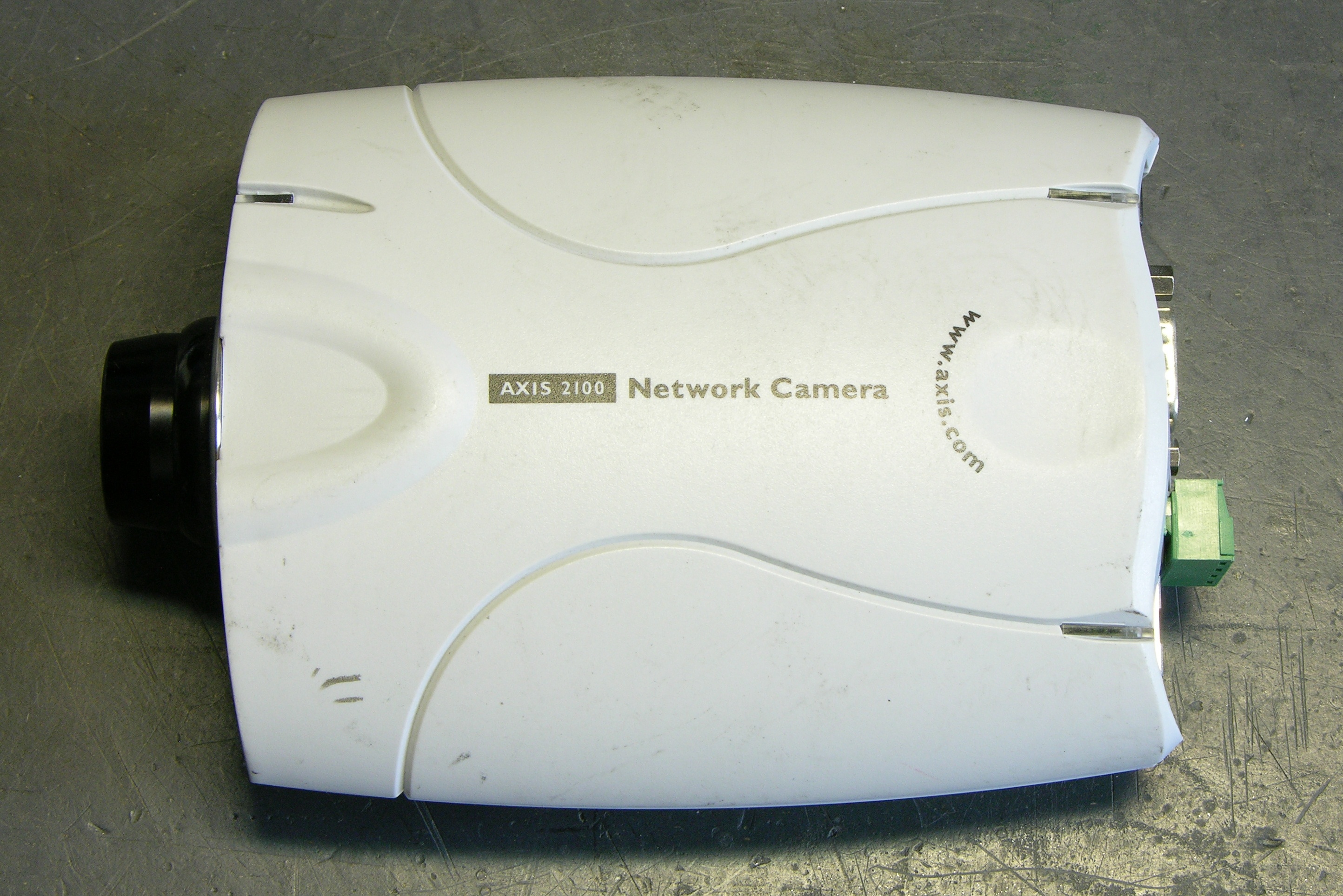
A little while back I bought a couple of used Axis 2100 network cameras, intending to use them at home (driveway cam? front yard cam?) to replace my lousy Linksys WVC54GC. The Linksys’s video stream is viewable only in Internet Explorer or with VLC; the Axis (although older) streams motion JPEGs that can be viewed with just about anything, provides still JPEGs, and has FTP server upload capabilities to update a statically-served image on a web server.

Axis 2100 network camera

Power Over Ethernet and Power Splitters

Having got them, I decided I’d like to play with one at work, installing it in our 3rd-floor bay window overlooking campus, so those of us with windowless offices can get a little sunshine in our lives. That would be easiest if we didn’t have to run both ethernet and power to the camera separately, so I started reading up on the camera’s power capabilities.

Power over Ethernet (PoE) is a standard for delivering 48VDC over an ethernet cable — depending on the implementation, possibly on the same pairs used for data, possibly on the spare pairs. The data pairs use differential signaling (the difference between TX+ and TX- is the signal, like balanced audio, as opposed to a single signal referenced to ground), so the DC power can be provided on the two wires of one pair and grounded on the two wires of the other pair (similar to the way phantom power is provided on balanced audio cable).

The product web page almost intimates that the camera supports PoE:

  • Access to a power outlet not needed with use of Power over LAN Midspan and Active Splitter from Axis
  • No need for power outlets and electrical cabling using Power over Ethernet products

But in fact the camera doesn’t operate when hooked to a PoE connection. Additionally, another Axis page lists a “PoE splitter” for the camera, which strongly suggests that power may be delivered over the ethernet cable by standards-based or non-standards-based means, but must be split externally before entering the camera.

Axis 2100 network camera, end view

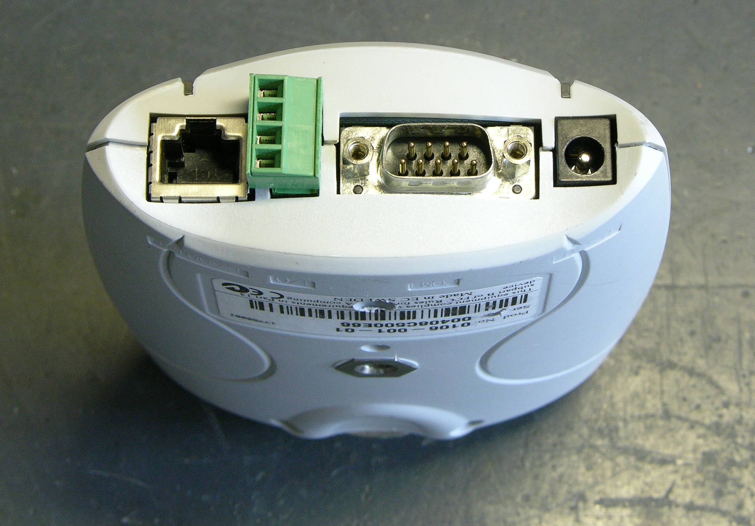
Still, pp 59 and 62 of the users guide show intriguing connections among the I/O port, the power connector, a bridge rectifier, and a switching power supply; and p 65 lists the power supply as accepting 9-15VAC or 9-15VDC, which is kind of interesting. Even though the unit clearly doesn’t function on PoE, I thought it was worth opening up to see whether it would accept non-standards-based power on the ethernet port.

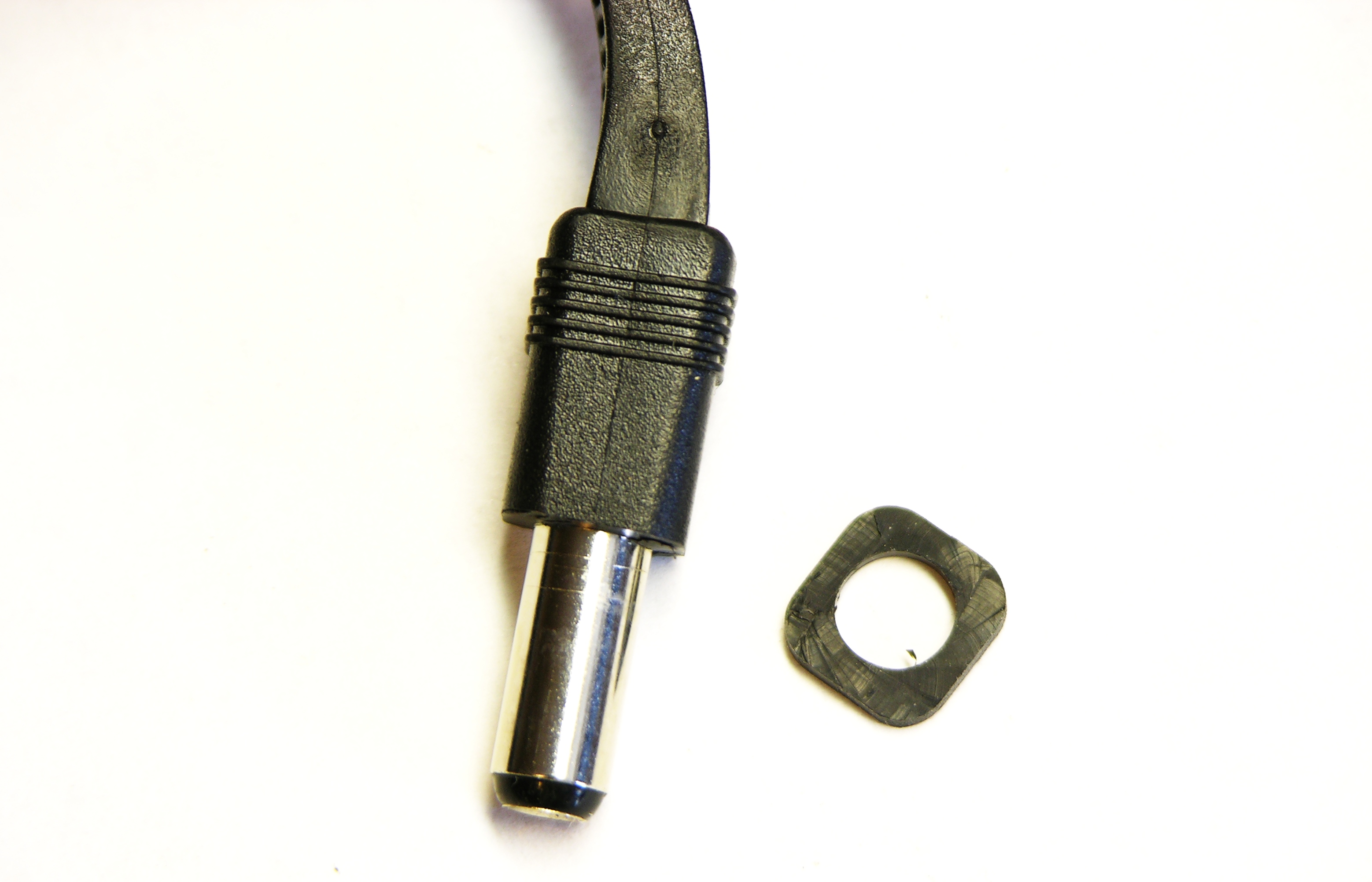
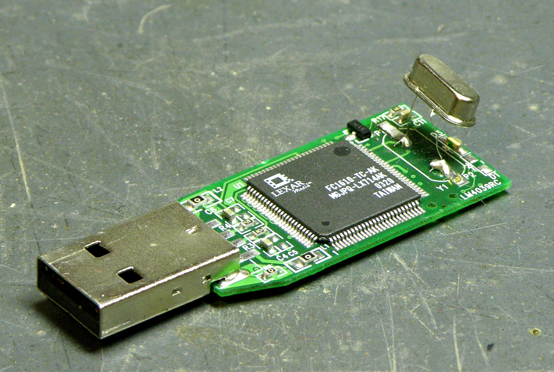
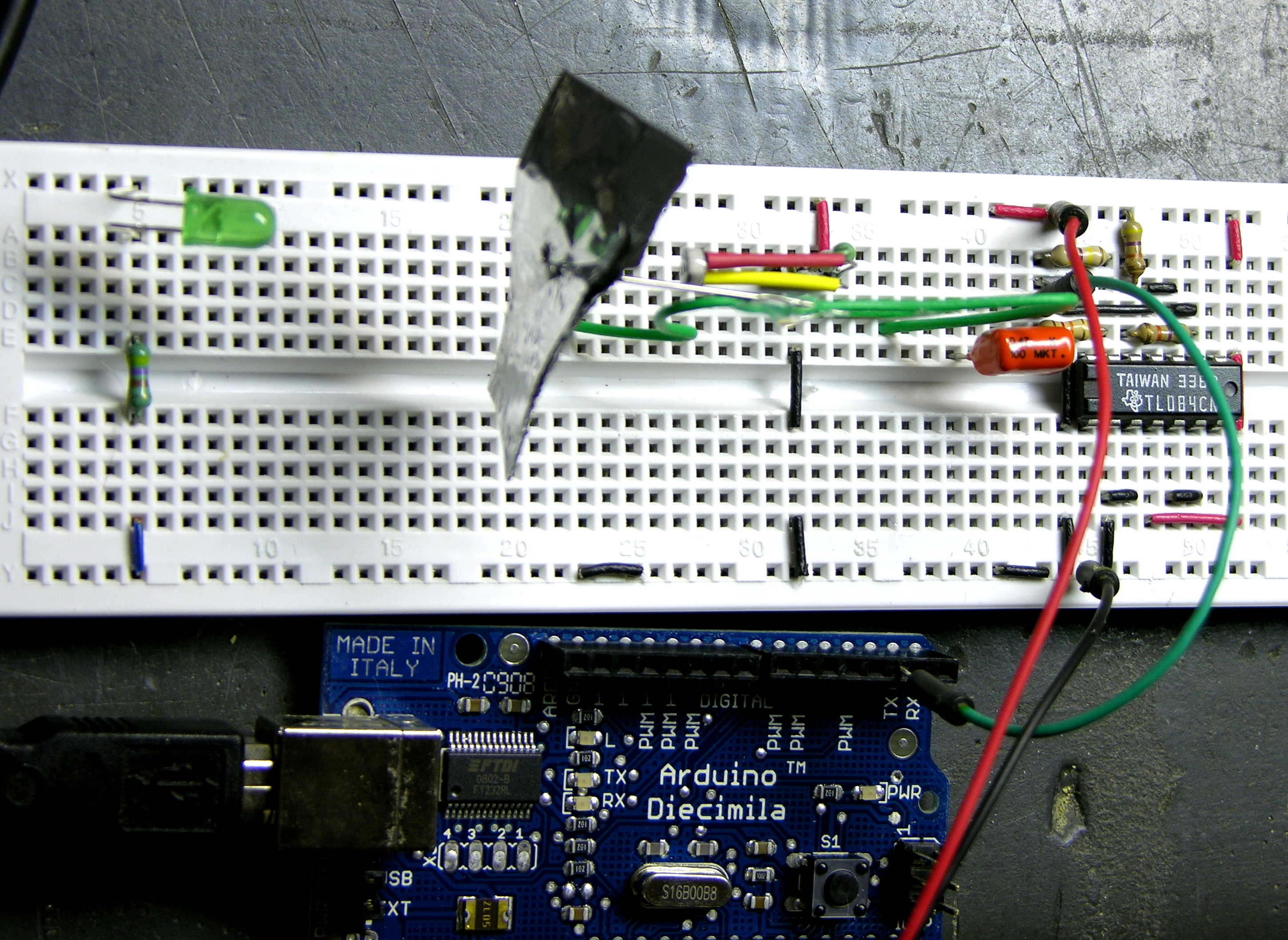
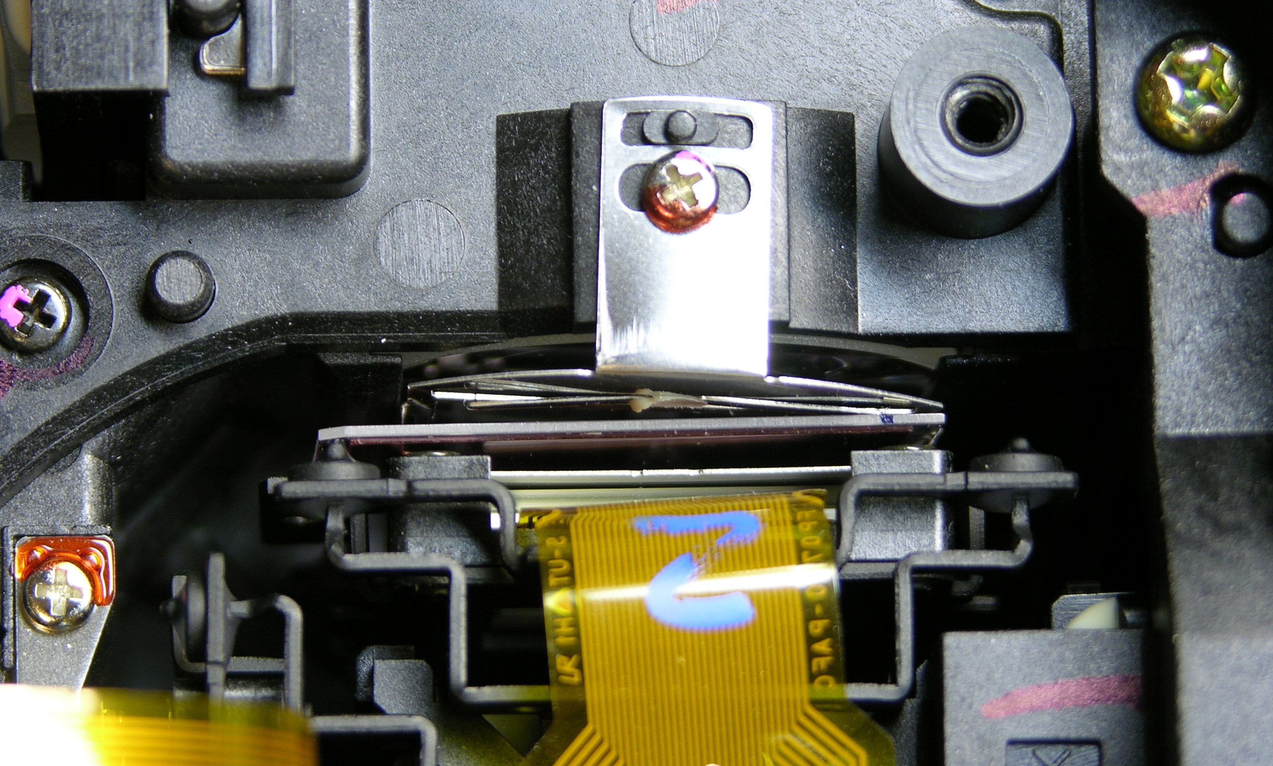
By the way, recognize that green thing?
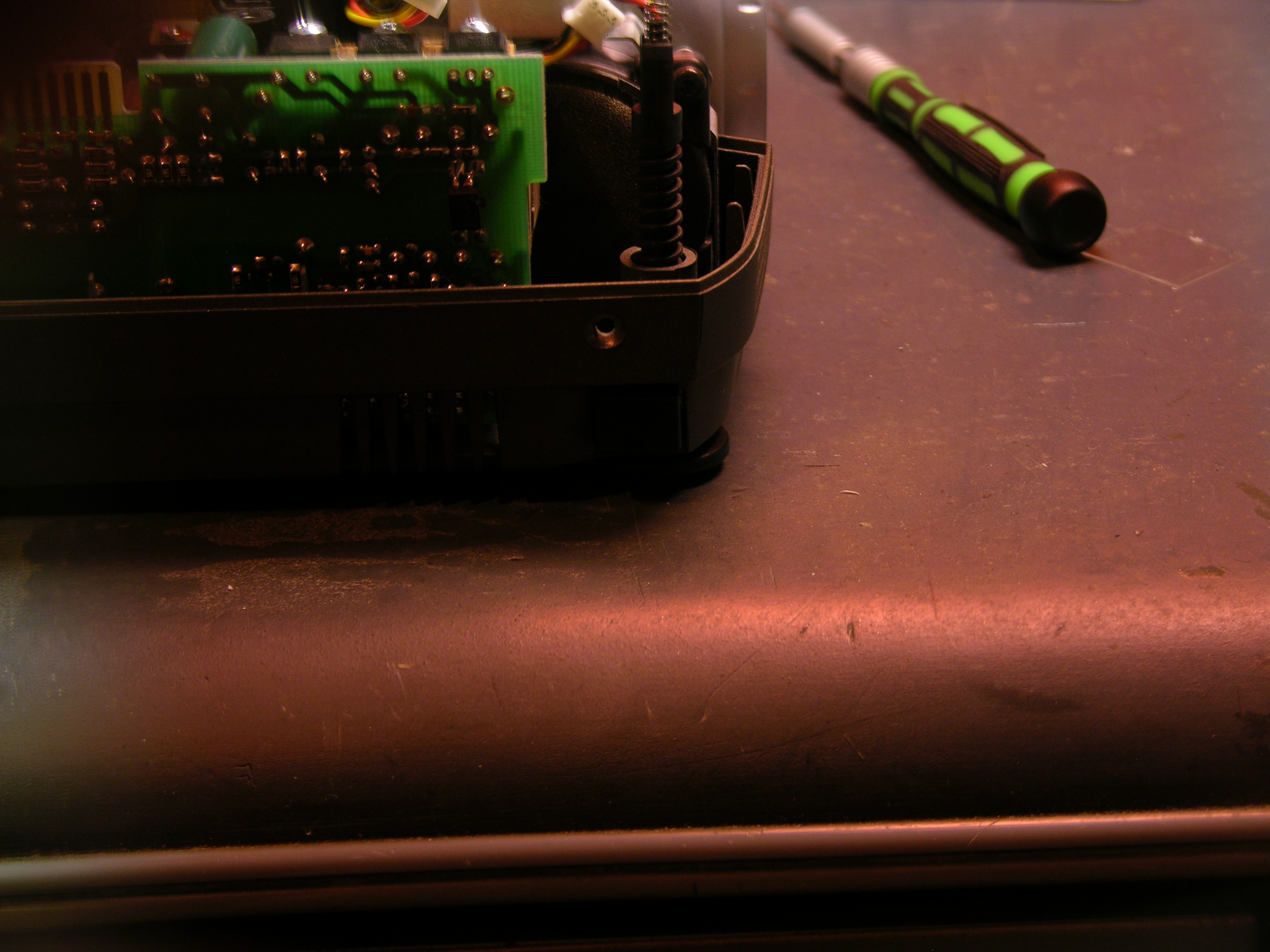
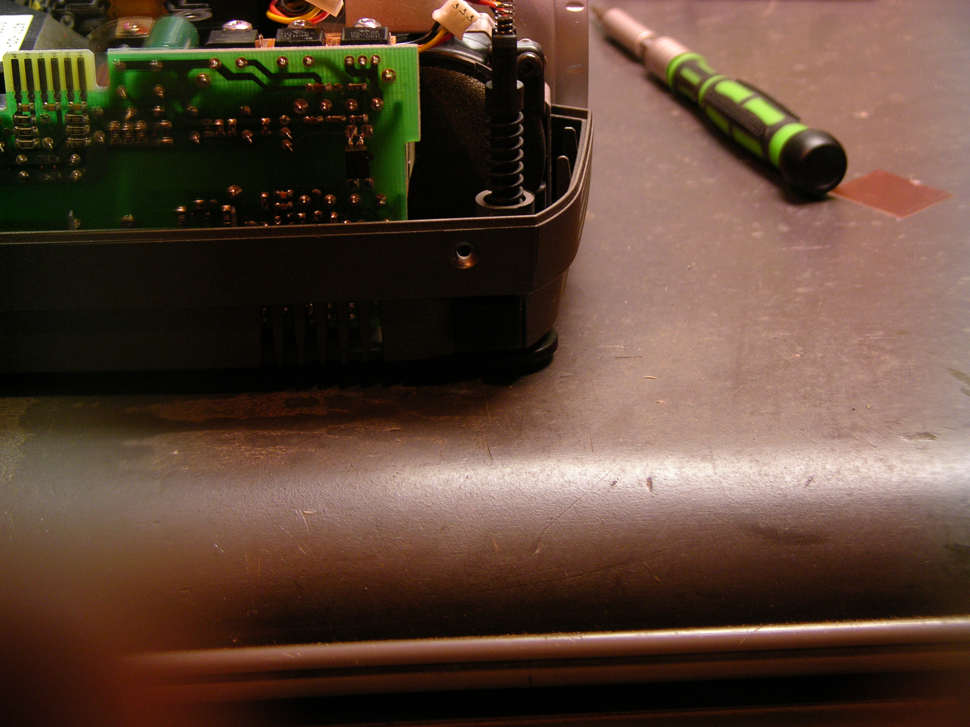
Going In

Axis 2100 network camera main PCB

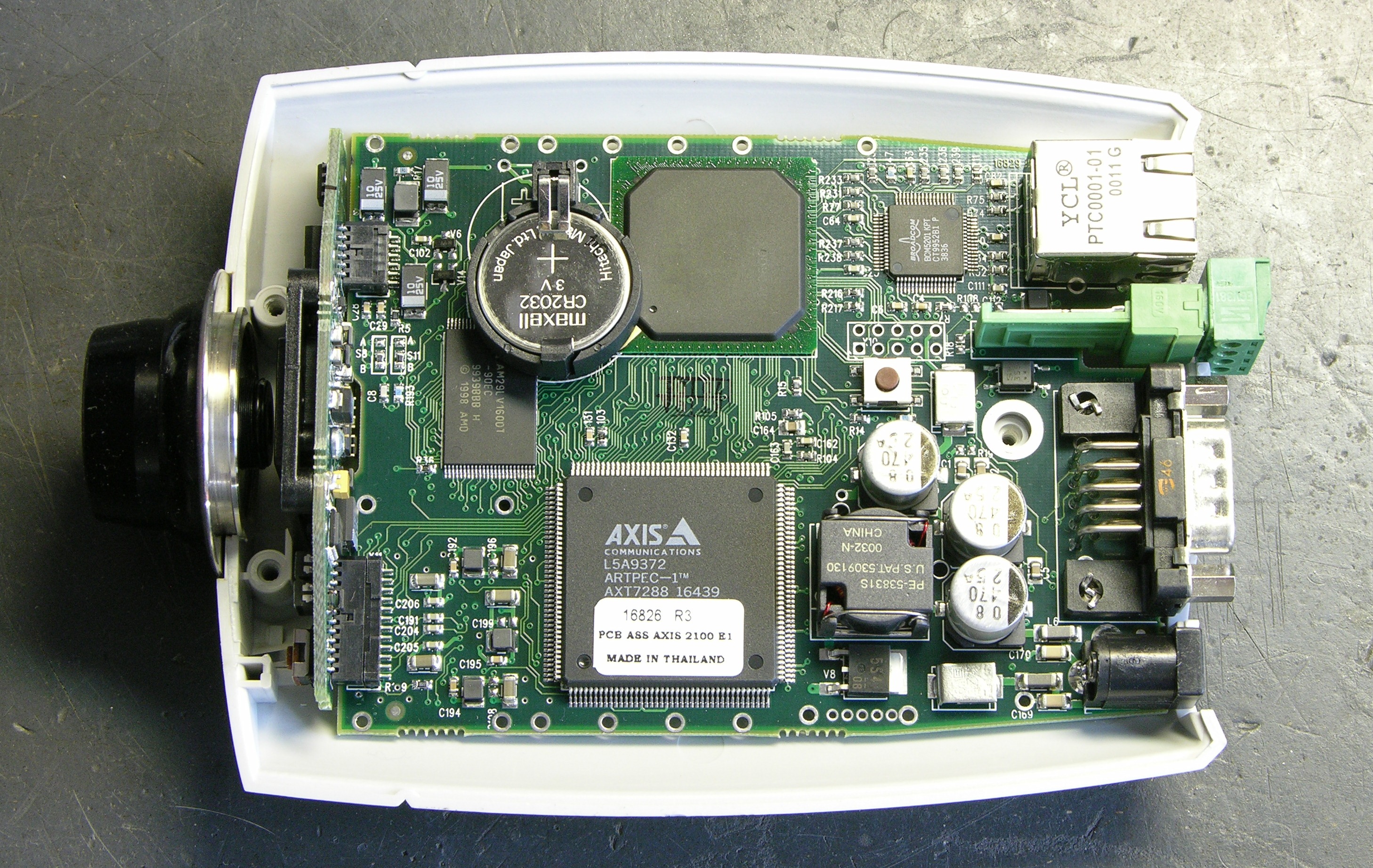
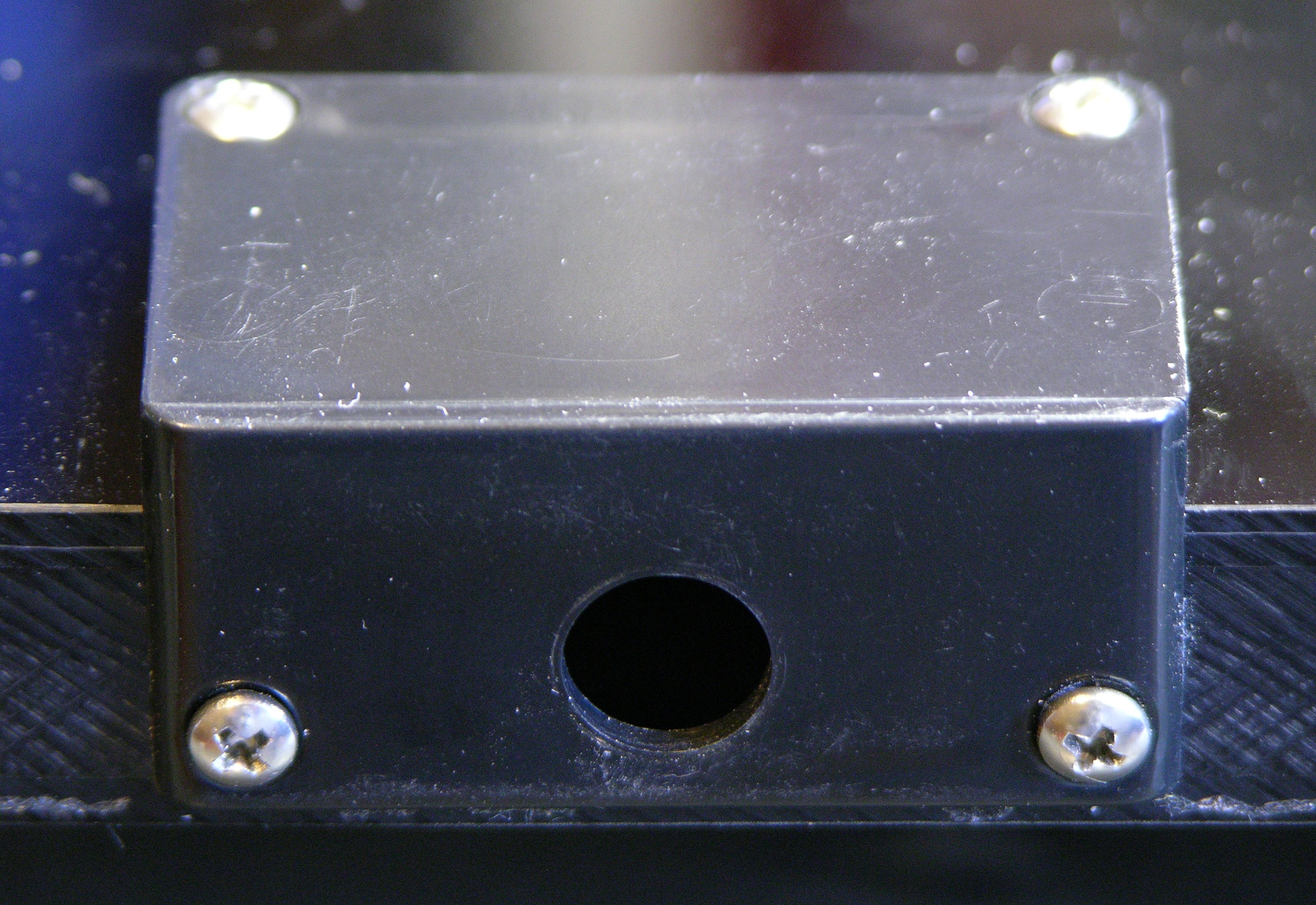
Here’s the camera with the bottom of the case lifted off. Note that the top of the circuit board faces the bottom of the enclosure.

Axis 2100 network camera CCD

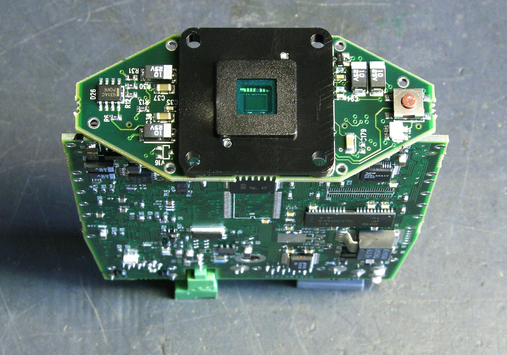
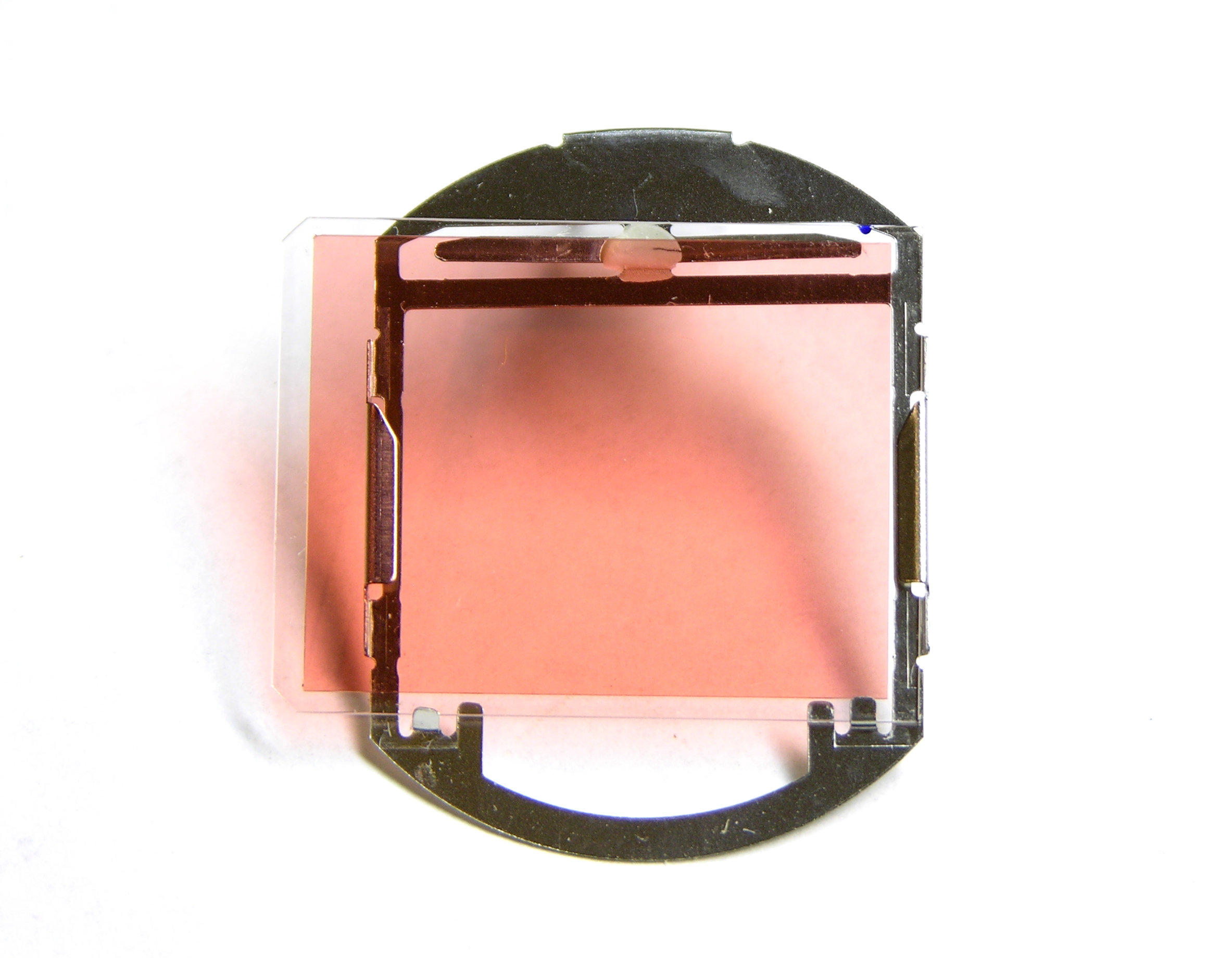
The CCD is on a separate PCB stuck onto the end of the main board.

Axis 2100 network camera PCBs

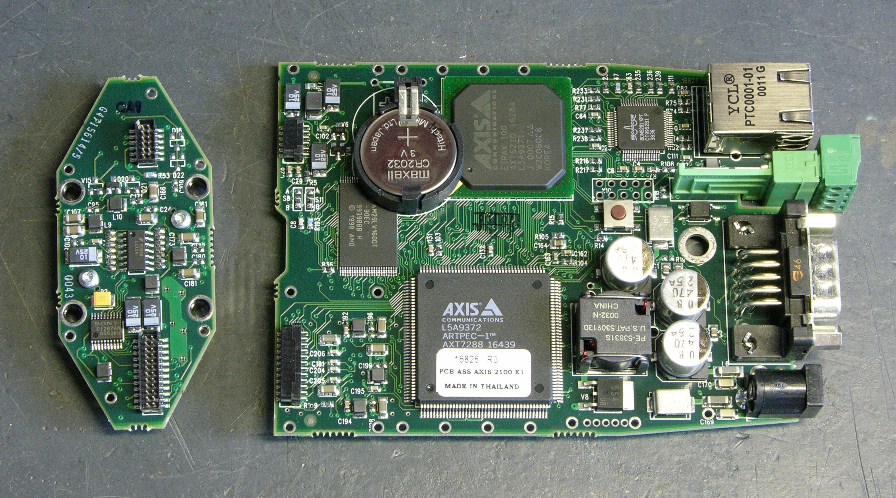
Another view of the top side of the board with the CCD board separated.

Axis 2100 network camera main PCB, back side

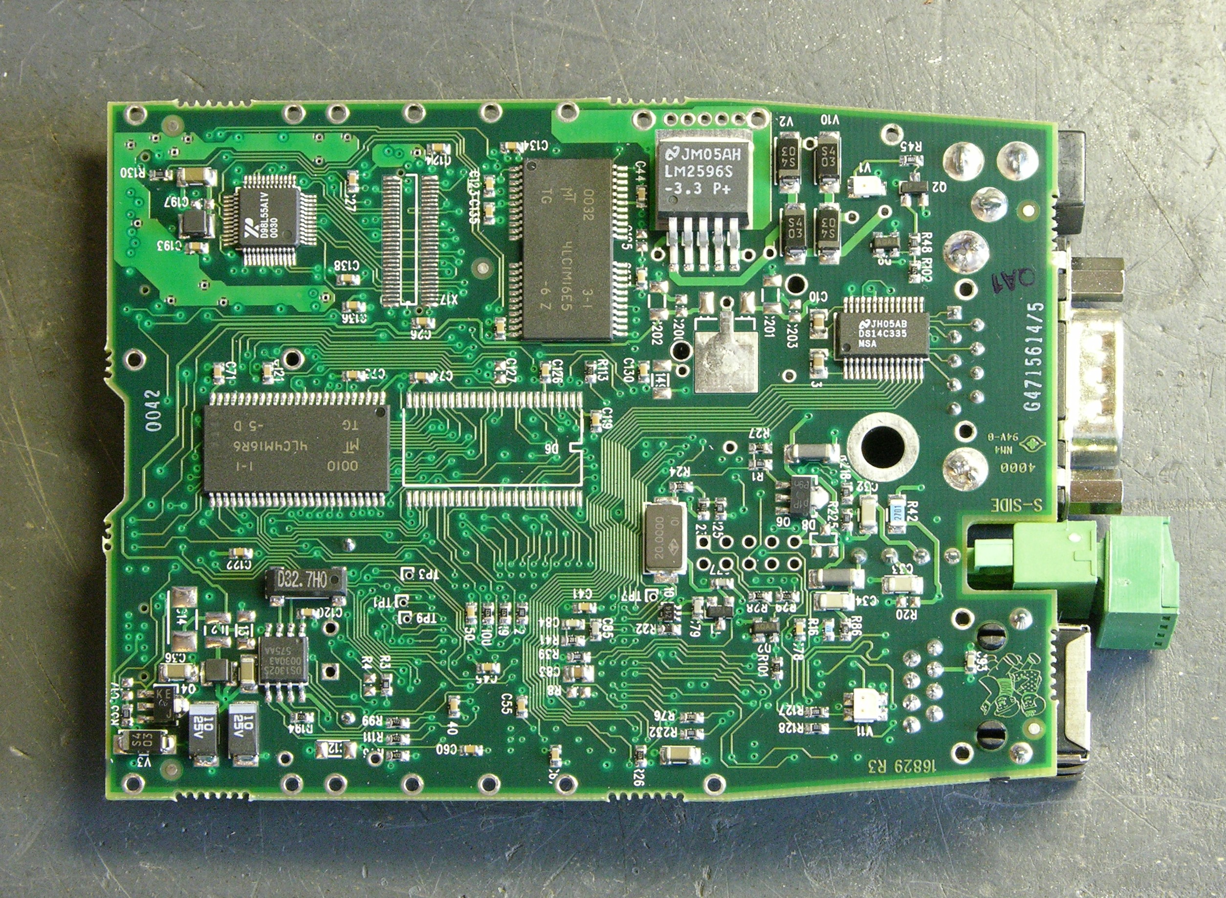
And the bottom of the board (facing the top of the enclosure).

Continuity

I started by trying to trace connectivity from the power jack to the unit’s ground, not remembering that the camera accepts AC input. I got no continuity there, as my tester doesn’t indicate continuity through diodes. After noticing the bridge rectifier (last photo above, just to the left of the upper right corner), I realized my error and was able to trace ground from the rectifier output throughout the unit.

Next I traced from the power jack to the I/O connector and confirmed the connections shown in the user guide — you can provide or draw rectified and filtered but unregulated DC power on the I/O connector.

Feeling bold from my discoveries, I checked continuity to the ethernet jack. I got DC continuity between ground and the center pins 4-5, but no other connectivity. Bah! No non-standards power on ethernet for me.

Hm, but I also hadn’t successfully traced V+ from the rectifier throughout the unit. I figured I needed to pick it up from the other side of the LM2596 voltage regulator — which turned out to be a switching step-down regulator.

LM2596

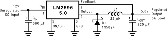
Pin 4 is the feedback that connects to the filtered, regulated output — and indeed, it connects to the V+ power supply pins of all kinds of things throughout the circuit. Cool; progress! Maybe the regulated DC voltage connects to the ethernet jack???

Mm hm, it sure does. I get DC continuity with .4-.5Ω resistance from the V+ rail to ethernet pins 1 and 2 (TX+ and TX-), DC continuity with .2Ω resistance to pin 3 (RX+), and no connection to any other pin.

So?

Although the datasheet’s application circuit above shows the 5V step-down regulator, the camera actually uses the LM2596S-3.3 for 3.3V power. That this appears on both TX pins of the ethernet port suggests that I could provide DC power on pins 1-2 and ground on 4-5.

But it would have to be regulated 3.3VDC, which (1) isn’t standards-based PoE and (2) isn’t going to travel well over 100+’ of cable. This suggests that a non-standards-based switch-end power injector directly in through the camera’s ethernet isn’t going to work well.

More plausible: Build a PoE-attached power supply with a 48V-3.3V step-down converter and hang it off the back of the camera. At first I thought that doing PoE would require a dedicated PoE chip to do the negotiation, but all that’s needed is a 25kΩ resistor across the powered pairs. So it really would be feasible to do, without a special chip just for the PoE.

However, if the solution is going to require external PoE down-conversion anyway, why bother going all the way down to the regulated 3.3V? Why not go 48V-12V and come in the regular power jack, which also eliminates any risk of making the LM2596 unhappy by feeding power into its output? (Its block diagram looks like that shouldn’t be a problem, but I don’t know enough to be certain.)

If using an external down-converter anyway, the only drawback I can see of splitting the power out to feed the the power jack separately rather than the ethernet is the requirement for an extra connector.

Or the Simple Way

Regardless, I don’t really want to have to build an external step-down regulator just to get the cameras working. So for now, I’m more likely to build simple cable splitters to inject 12V onto unused pairs at the switch end and split it out to the power jack at the camera end.

Fixing an LED Sign

Sunday, March 1st, 2009

My wife is working a couple of evenings a week for a tax preparer who used to work for her when she was an H&R Block office manager. Friday night he was taking down his $300 sign out of the window to throw it away because it had a few dark LEDs. She told him no promises, but I might be able to fix it because I do stuff like that every night.

And yeah, she was right.

LED income tax sign with dark LEDs

I’m actually not sure I’ve seen all the failures the sign has to exhibit, but I’ve fixed two overt and two covert. The obvious ones were the dark LEDs in the white “M” and “E.”

LED sign pull-chain switch

The less obvious ones were that the pull-chain switch at the bottom doesn’t shut the sign off, and that the DC power plug pops out of the jack.

LED sign DC power jack, head-on view

Opening It Up

The sign is made of two plastic sheets sandwiching a thicker plastic frame. The front must be glued on, but the back is screwed on for repairability. Actually, given what the inside looks like, I have my doubts that the manufacturer ever considered repair; I suspect screwing the back on was just the first thing that occurred to them.

Interior wiring of LED sign

I’m (mostly) not knocking the schematic — many parallel series chains of LEDs is the only reasonable way to design something like this. And making chains of three each blue and white LEDs but five red LEDs is also reasonable, given the respective voltage drops.

But I do take issue with stacking three LEDs with 3V drops on a 9V (nominal) unregulated power supply. The supply happens to run about 9.7V under the load of the sign, which leaves .7V across the 150Ω current-limiting resistors, hence just under 5mA LED current.

Leaving that low a voltage drop across the resistors makes the LED current (and brightness) incredibly susceptible to variation in the actual voltage of the unregulated power supply: a power supply change from 9.7V to 10.4V seems insignificant but would double the (white and blue) LED current. Worse, a drop from 9.7V to 9.35V would halve it.

LED sign wiring closeup

Mainly, though, it strikes me odd that the sign is wired with leftover four-pair UTP (network cable). Was this thing built in some guy’s garage with stuff he pulled out of the dumpster at work? (Wait, did I build this thing??? ;-) )

Fixing the Power Connection

First things first — I started with the power connection so I wasn’t fighting it the whole time I was testing and repairing the rest of the sign.

LED sign DC power jack, side view

The jack is recessed into the frame. The manufacturer made some effort to get it close to the outside and minimize the amount of recess; but the correct recess for this jack is zero. The plug is designed to make good mechanical contact when it’s sunk completely into the jack; before that point, the springiness of the jack’s outer contact pushes the plug back out of the jack, which is exactly what was happening.

LED sign DC power plug, cut to fit recessed jack

The solution, or I should say hack, was to remove a corresponding amount of rubber from the plug’s molded barrel insulation, so it could once again fit the depth of the jack properly. No further problems.

Dead LEDs

Next I tackled the dead LEDs. A series string of three was dark in the M, leading me to supect one LED burned out and open. Measuring the voltage drop across each, I found the entire ~9V drop across the uppermost LED, so it appeared to be open.

Jumpering across open series LED

After jumpering across the suspect LED, the other two in the string lit (of course, too brightly relative to their peers), so it was indeed open and the problem.

The right fix would be to replace the broken LED, but I don’t have any white 10mm LEDs on hand, it would take a while to order, frosted 10mm LEDs seem to be more difficult to find (or to find clearly specified as such), and I’d have to wade through long lists of nearly-identical products searching for the one that was actually right.

Immediately I thought of a way I could fix it using materials I had on hand — drill a hole into the back of the 10mm LED and sink a white 5mm LED into it. This idea made me cackle with glee, so you can imagine my disappointment upon realizing I don’t in fact have any white 5mm LEDs here. I need to get me some so I can go back and try that yet. :-)

SMT LED soldered across burned-out 10mm LED

Really, this hack is just as good, though. (Ah, I realize I’m using the word “good” in a perhaps somewhat nontraditional sense.) The SMT LED soldered across the dead 10mm LED’s pins diffused nicely through the 10mm LED lens.

There was also one lonely dark LED in the “E.” Turned out when it failed, it didn’t open, so it was still passing current through for its friends.

SMT LED soldered onto burned-out 10mm LED

I used the same hack on this one, although I did clip one lead off so that the dead LED wouldn’t pull the voltage drop too low for my SMT LED.

I was surprised at how well the hacked LED in the “M” matched the brightness and color of the other white LEDs, given how different its physical construction is. The one in the “E” is a little more noticeable (picture down below), but probably not objectionable if you’re not specifically looking for it. And I’d say a replacement 10mm LED has fairly good odds of being a little off in color or brightness, too.

At 5mA I should have nothing to worry about; but I watched the first SMT LED with my infrared thermometer for a minute with the power on, and it didn’t get above ambient temperature. Should last a good long time.

“Fixing” the Power Switch

I got the pull-chain switch out of its housing and couldn’t see why it didn’t work. Since my wife said the owner leaves the sign on all the time anyway, I don’t reckon it’s worth replacing the switch, so I removed it and soldered in a bypass wire.

Because the switch was broken in the “on” setting, I could have left it installed and the sign would be on. But the switch is already broken, and who knows when it’ll further break “off” instead of “on.” Under the circumstances, I’d rather bypass it now than have to go back and reopen the case to replace the switch later.

LED sign empty pull-chain switch housing

There’s a sizeable cutout in the bottom edge of the back cover for the switch, so it wasn’t really an option to leave the switch cover off. It does look a little odd having the cover on there with no switch protruding, but it’s not awful.

Putting It All Together

LED income tax sign, repaired

And thar she be, in all her working glory. For the moment, anyway.

Shortly after taking that picture, I moved the sign and a couple of blue LEDs on the border went out; then one of them came back on. Half an hour later, both (all) were back on. I’m not sure I’ve seen the end of this yet, and I may have a sizeable job cleaning leads and resoldering cold joints sometime in my future.

Physical Construction

LED sign corner assembly

One last thing: the frame and skin construction of the sign forms a rudimentary torsion box. The plastic face and back are quite flimsy by themselves, and even the face with frame glued on was flexing as I was moving it. But the moment I got the back skin screwed on, the entire assembly was quite rigid and immune to flexing and racking. Pretty impressive for such a simple technique.

Fixed a USB Thumb Drive (Sort Of)

Friday, October 3rd, 2008

USB thumb drive, repaired

A couple of weeks ago, Matt from the desktop support group at work asked me for soldering advice / demonstration. Someone he supports kept all her data on a USB thumb drive with no backup, and it stopped working. When he opened it, he found the crystal had come off the board, and he wondered whether I could solder wires to it well enough to get the drive working and retrieve the data before discarding the drive.

It turns out the crystal was a through-hole design that had had its legs crimped into flat strips, then bent out sideways to surface-mount. (You can see the pads where it was originally mounted.) But that created stress points at the end of the crimped area where the leads were bent, and the owner treated the drive roughly enough (I think attached to her keychain that she dropped onto the counter every night) that both legs sheared clear off.

Didn’t leave me much to solder to, either, but I got it done. Matt’s too young to know wire wrap and didn’t have any on hand, but I found some stranded wire and used a single strand. It wasn’t an elegant job, but it was sturdy enough to survive some handling, and it actually worked. In spite of his professed faith in my abilities, Matt was amazed and delighted when he plugged in the drive and the contents popped right up on his computer.

And I get to keep the repaired drive as my reward. Which naturally means that I’ve already broken one of the wires. :-)

Free UPS + Free Batteries == Hammond Organ

Saturday, September 27th, 2008

UPS that someone gave me because it didn’t work:

Minus its original batteries, apparently slightly past their prime, which I had to pry out of the case by levering with a big screwdriver:

Overheated gel cell batteries

Plus three-year-old unused batteries from the campus fire chief:

Equals I can play my “new” Hammond organ, which is temporarily in storage where there’s no electricity:

Worth noting:

Cold Start
When the UPS is off and there is no utility power, it is possible to cold start the UPS to power the loads from the UPS’s battery.
Note: Cold start is not a normal condition.
Press and hold the on/test button until the UPS begins beeping.
Release the on/test button during the beeping to start the UPS.

Addendum 29-Sep-2008:

Runtime with a 15W wall wart plugged in was about an hour. Runtime with the Hammond plugged in (after fully recharging) was about three minutes. I guess free batteries are worth what you pay for them . . . but I do now know that the UPS works and is worth replacing the batteries.

Wire-Scrounging Challenge

Tuesday, August 5th, 2008

I brought my “Arduino on the go” along to New Mexico, but discovered I’d installed a pushbutton on the breadboard in a spot that was already wired to ground, making the button always “pressed.” In order to move it, I needed more jumper wires; and due to a combination of hurry and hubris, I had brought none along.

I needed some 24- to 26-gauge solid wire, in a cabin, on a mountain (excavaaaaaating for a mine). The nearest Radio Shack was twenty miles and about forty minutes away, and I couldn’t think of any store in Angel Fire likely to have wire for me.

So, where would you scrounge up wire in an emergency? I’m actually interested in suggestions — add them to the comments if you can come up with something other than my ideas. I didn’t have anything along that I could take apart for wire, I didn’t have a soldering iron to tin stranded wire, and I wasn’t willing to damage anything in the cabin, the car, or the area.

(more…)

Arduino MIDI Volume Pedal

Saturday, July 12th, 2008

I’m playing keyboards this fall in another rock concert to benefit the high school robotics team, and for some of the tunes I need to be able to fade an organ in and out over a period of a measure or two. My keyboards are velocity-sensitive, so if you hit the keys harder they play louder (like a piano); and they have aftertouch, so if you press down extra-hard on the keys you can get special effects. But there’s no good way to change the volume of their organ sounds dynamically, and these synths don’t have inputs for volume pedals.

This is the MIDI volume pedal project I was starting to work on when I took apart a Baldwin organ swell pedal and decided to leave it intact based on what I found inside. I got another analog volume pedal from a pile of unknown origin at the school lab and finished the job.

Homebrew MIDI volume pedal using Arduino

(more…)

Free: Boxed Manuals → Cases for Prototyping On the Go?

Wednesday, June 25th, 2008

I’ve been saving these relics of the Information Age forever, initially because I had the computers to go with them, then out of nostalgia, then because I forgot I had them, and now because it seems like the boxes should be useful. But really, I’d just like them to go away.

Anybody want some three-ring binders with matching boxes, maybe to put an Arduino and breadboard in to take with you on vacation and play with circuits when you’re stuck in Saint-Tropez for a couple of weeks with nothing to do? The rings oughtta be good for holding baggies of parts, or something.

Seriously, if anyone wants any of these, they’re yours for the cost of shipping. The MS-DOS Operating System is missing one of the two volumes from the double-wide case; the Wordstar and Operating Instructions are intact in single-wides.

“Airduino” Scungy Anemometer Part 2: Digital Connections and Interrupts

Sunday, June 8th, 2008

In part 1, I described making a propeller out of foil to measure the airflow of my air conditioning system, building an optointerruptor from an LED and a CdS photocell, and amplifying the signal to a usable level.

Next, I needed to feed the signal into a digital input on the Arduino. Old-school digital inputs don’t like having analog signals fed into them; but I knew from working with a PIC that some of the Arduino/ATmega pins would probably have Schmitt-trigger inputs, which have hysteresis.

A digital input with hysteresis turns on when the analog input becomes higher than an upper threshold but doesn’t turn off until the signal falls below a lower threshold. The effect is that an analog signal wandering back and forth around the midpoint doesn’t cause lots of twitching back and forth of the digital interpretation. Regular thermostats work this way — they turn on your AC when the temperature gets one-half to one degree above the thermostat set point, and turn off the AC when the temperature falls one-half to one degree below.

Schmitt-trigger on ATmega input

So imagine my delight to find that every ATmega8/168 input pin has Schmitt-triggering. Any pin would do! But I had two particular ones in mind . . .

External Interrupts

All I wanted the program to do was count how fast the propeller blade went by, activate a relay when it got above a higher speed, and deactivate the relay when it got below a lower speed (hysteresis again, at a different layer of the system). For a program that simple, I could write a loop to watch the input pin in software . . . but why, when the ATmega can do it in hardware?

(more…)

“Airduino” Scungy Anemometer Part 1: Detection and Amplification

Sunday, June 8th, 2008

Necessity is said to be the mother of invention, and 90+°F daily temperatures with the air conditioner on the fritz made me feel pretty inventive.

Arduino anemometer, angled view

Our air conditioner was low on refrigerant and the blower fan motor may be running slower than spec and not moving enough air. Between the two problems, the expansion coil inside the furnace housing would ice up, over a few hours completely blocking the airflow and preventing any meaningful heat exchange. I’d then have to switch off cooling mode and run only the fan for a few hours to melt the ice.

On a weekend when I was home all day, I discovered that I could keep the house fairly cool by setting the blower fan to run all the time, manually monitoring the airflow out the vents, and cycling the AC off when airflow was restricted and back on when it opened up. Which sounded like a perfect job for a microcontroller.

Introducing the scungy anemometer, or Airduino v0.1, for short. Also introducing real-life code using the Arduino’s external interrupt pin(s).

(more…)

Repairing an InFocus LP290 Projector, Part 2

Thursday, May 8th, 2008

Last fall I bought a used InFocus LP290 projector, and in January I opened it up and found that the polarizing filter for the blue LCD was melted. Since then I’ve been keeping an eye out for a replacement filter, and Monday night I parted out a dead Optoma projector from Jeremy for the polarizers. Tonight I fitted one to the InFocus, with surprising success.

LCDs and Polarizing Filters

A long time ago, I think I knew how LCDs work, but I’d forgotten until a great conversation I had with Dave, who posts comments here from time to time and is immensely knowledgeable about LCDs. To paraphrase:

In high school physics, we learn that light behaves as both particles and waves (both of which can be demonstrated experimentally). In the wave model, light is a transverse wave: it “wiggles” from side to side in a plane containing its line of travel. (In contrast, sound is a longitudinal wave — it makes compressions and rarefactions back and forth only within the line of travel.)

Normal light has waves wiggling in all directions around the line of travel — up and down, side to side, and all angles in between. A polarizing filter only lets through light waves wiggling in one particular orientation, say up and down. It also lets through the up-and-down component of waves wiggling at an angle other than up and down; but waves wiggle side to side have zero up-and-down component and get completely block.

Digression: polarizing filters are used in photography and in sunglasses to block glare. It turns out that the light waves in certain kinds of glare have been polarized by their reflection off the surface of whatever object is glaring, and polarizing filters can completely block those types of glare. It’s a really cool effect to rotate a polarizing filter in front of something that’s backlit at a fairly steep angle and watch the glare appear and disappear.


I have this description backwards. See Dave’s comment for an excellent description of how it really works.

Back to LCDs: the crystals in LCDs pass light waves untouched when they’re inactive, and twist the polar orientation of light waves when active. This is the key to how LCDs work.

An LCD screen like on a cheap calculator has a polarizing filter in front, the LCD panel, and a backing mirror. Light from the room hits the filter and only the portion in the proper orientation (say up and down) passes through. That light then passes through the LCD, and where the LCD is inactive the light maintains the same orientation. It reflects off the back, passes through the LCD untouched again, and is already in the correct orientation to pass through the polarizing filter on the way out. Thus where the LCD is inactive, you see light areas.

Where the LCD is active, it twists the polarization of the light waves by 45°. (There are other possibilities, but I’m talking about simple and cheap.) It reflects off the mirrored back and passes through the LCD again, getting another 45° of twist for a total of 90° with respect to the polarizing filter. That’s exactly the angle of polarization that’s completely blocked; so where the LCD is active, you see dark areas.

In projectors, with light passing through the LCD only once, it has to work a little differently. I’m guessing the LCD does 90° of twist, with polarizing filters both before and after.


So without the “before” polarizing filter in the blue light path of my projector, the darkest the blue beam could ever be was about medium-bright, because it only got half as filtered as it was supposed to. Instead of true blacks, I got medium blues. White was still white, of course, because that’s where the light was supposed to pass through (and still did).

Colored Polarizing Filters

Looking at the optics inside projectors, there are lots of things reflecting, refracting, and filtering light, and I often see color tints and have trouble determining which thing I see is the color filter. So after taking the first polarizing filter off the Optoma and finding it to be a dark blue-grey, I thought it was a neutral grey and didn’t think any further about color.

Tonight I found that each polarizing filter is a different color, complemenrary to the color of the light path it’s installed in. I was having trouble figuring out why you’d want to have a color filter and a polarizer. Since the yellow-orange filter blocks blue light in the blue beam, it seemed it would simply dim the blue beam all around. Okay, that leads to blacker blacks; but (apparently) in the same way as just using a dimmer bulb. That didn’t make any sense.

Then I looked through the colored polarizing filter more carefully.

Desk viewed through orange polarizing filter from projector, sideways

Desk viewed through orange polarizing filter from projector, vertical

The two pictures are taken with the same camera settings, the first with the orangey filter held in front of the lens horizontally, the second vertically.

Both pictures have the orangey cast to them, but notice in particular the color of the glare on the edge of my desk. In the second picture, it’s nearly white, not orangey like everything else. That’s where the glare is.

I believe this filter passes all colors of light in general, and specifically blocks blue light that has opposing polarization. That’s why the screwdriver looks about the same in both pictures — everything except blue gets through, and the light from the screwdriver isn’t polarized so the blue is blocked. The glare on the edge of the desk is polarized, so even the blue gets through and gives a more even white.

That’s kinda cool. And that means the filter should do an extra good job of darkening blues where the LCD is active. With a complementary-colored filter in each of the three color beams, it means it should do a really good job of making black blacks.

Fitting the Filter to the Projector

The InFocus and Optoma obviously don’t use the same size filters, as the Optoma filter clearly doesn’t fit the InFocus carrier. Fortunately, the Optoma filter is larger, so at least I can hack it to work.

Projector polarizing filter fitted into different carrier

(The camera doesn’t represent the filter color very well, by the way. In real life, it looks very similar to the deep orangey-yellow of yellow liquid food coloring, not as pink as it looks here.)

I confirmed the proper orientation for the filter by very carefully slipping it into position in the projector and holding it there with a needlenose pliers with the projector running, and the proper orientation is horizontal. Too bad, since the Optoma filter was as tall (short dimension) as the InFocus carrier is wide (long dimension), and it actually fit really well in the carrier the wrong way.

But with a little bending of the carrier edges, I got the too-large filter secured in (and hanging out of) the carrier well enough to reassemble the projector. The glass isn’t parallel to the carrier any more, but I can’t think of any reason that’ll make a difference. You can see the glass slide sticking too far to the left, and slanting forward, in this picture, between the silver carrier mounting tab above and the LCD housing below.

Hacked polarizing filter installed in projector

The projector works now, and the blacks are black again! I’m not ready to close it up and call it done until I sit next to the projector and test it for an evening to make sure it’s not going to melt down and light my house on fire, but I’m optimistic. And if it works, I’ll think about cutting down the glass the filter is mounted to, so it fits properly.