Assembling the MakerBot CupCake Extruder

May 18th, 2009 by Keith Neufeld

I’ve been plugging away at the CupCake “Plastruder” in the evenings, and I now have the mechanical assembly mostly finished, pending the arrival of some custom parts.

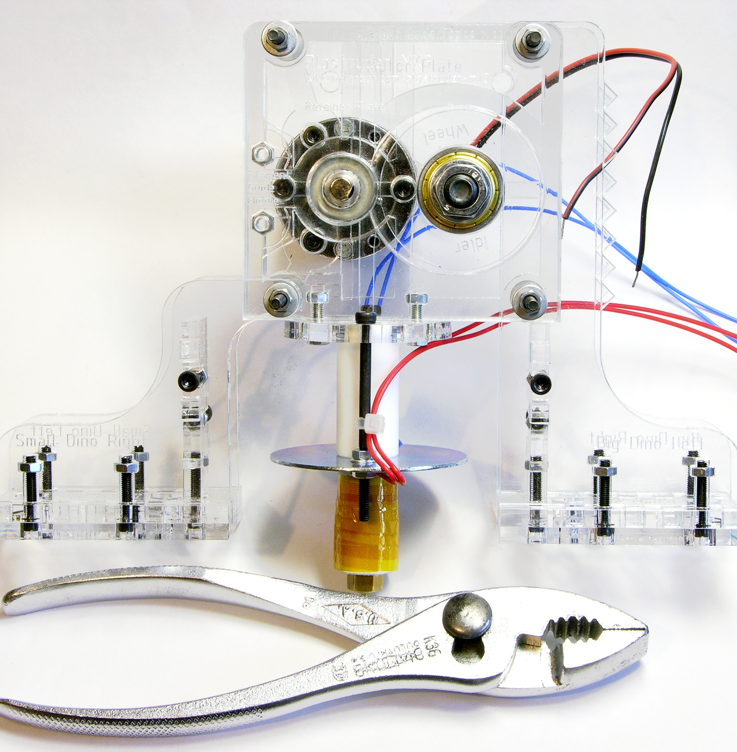
MakerBot Plastruder plastic extruder

I’m delighted by the clear plexiglas design. And having the mechanical assembly — particularly the extruder — put together really highlights how small this thing is. That’s not a bad thing — for a given build capacity, the smaller the machine is, the better.

Read the rest of this entry »

Soldering the MakerBot CupCake Extruder Controller

May 8th, 2009 by Keith Neufeld

Over the last two evenings, I got my CupCake’s extruder controller assembled.

RepRap extruder controller

I have just a few notes below following up on solder paste, hotplate soldering, and missing and unlabeled parts.

Read the rest of this entry »

Assembling the MakerBot CupCake Stepper Controller (or My First Reflow Solder)

May 5th, 2009 by Keith Neufeld

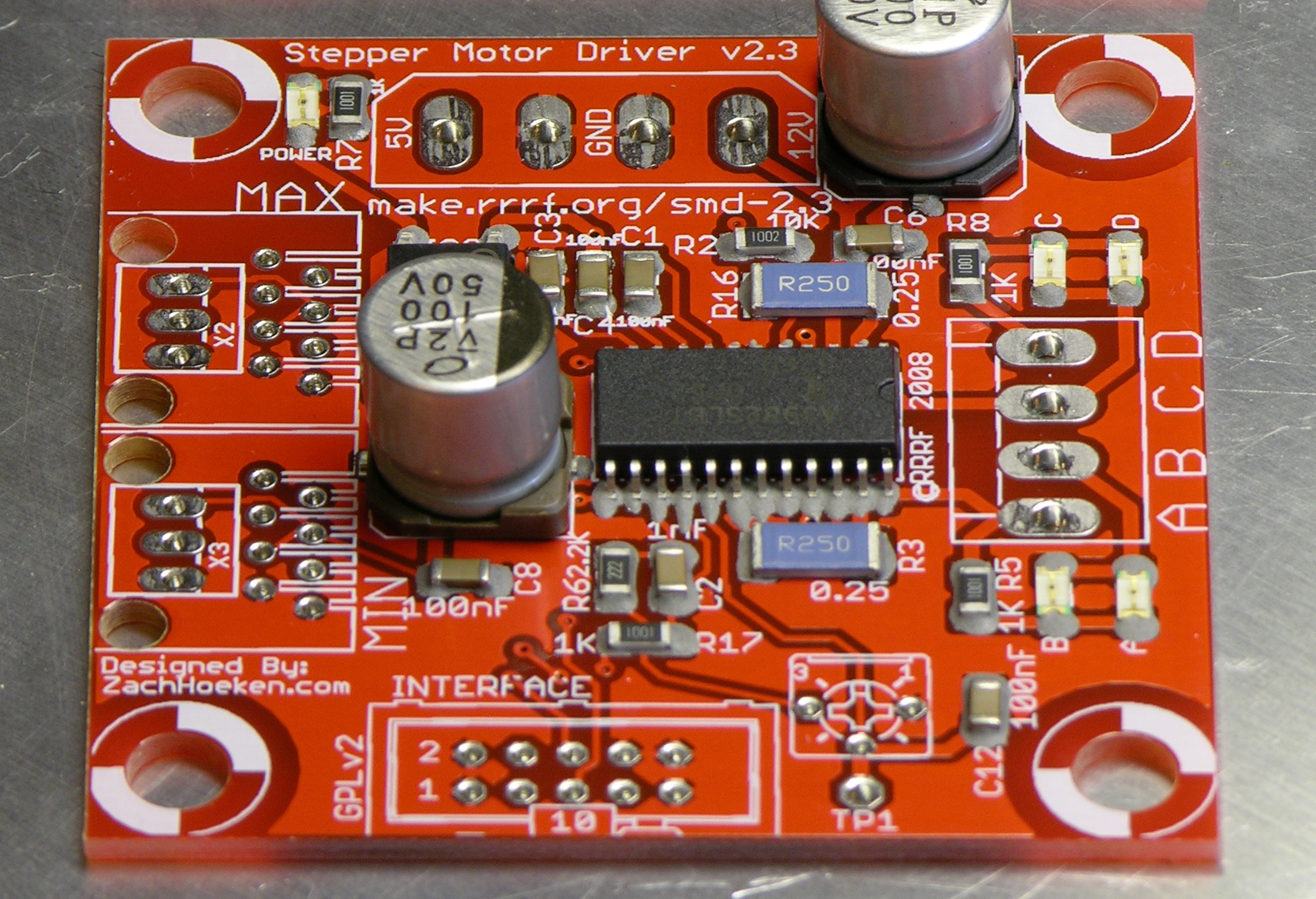
Having got my reflow soldering hotplate assembled Sunday, last night I sat down to build the first stepper controller for my CupCake rapid prototyper. Besides being the first of the CupCake’s stepper controllers, this is also the first thing I’ve ever reflow-soldered, EVAR (although not the first SMT I’ve soldered, as I’ve done that by hand before).

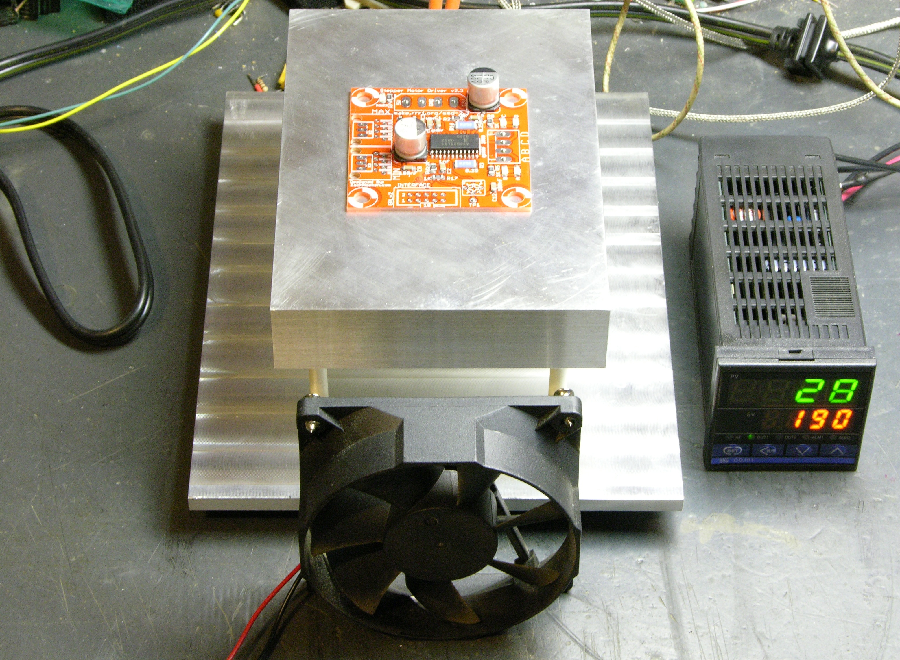
RepRap (MakerBot CupCake) stepper driver on hotplate, assembled and ready to reflow solder paste

There are lots of solder paste and solder reflow tutorials online, and that this ain’t. This is just my observations about parts of the process I hadn’t previously picked up from reading.

Read the rest of this entry »

Copycat PID-Controlled Solder Hotplate

May 4th, 2009 by Keith Neufeld

In early February, a correspondent pointed me to Jeff Keyzer’s mightyOhm blog. I immediately ran across his homebrew PID-controlled soldering hotplate and improvements, and immediately knew I had to have one.

I contacted Jeff through his blog and he was great about sharing his knowledge. He’d built his hotplate using the last of some surplus parts he’d picked up at a now-closed store in the Valley and was considering ordering a batch of parts to make a few for all the folks inquiring about them, but hadn’t done so yet. I was eager, decided it’d be quicker to make my own (and three months later, that may actually have been correct), and went off to eBay to find myself some parts. I also bought aluminum and took a practice run at polishing it.

Most of the CupCake PC boards are SMT; and although I’m very comfortable soldering SMT by hand, I really wanted to get my hotplate up and running and use the CupCake boards as a chance to try out reflow soldering. (That’s why I started by assembling the opto endstop boards, which are the only all-through-hole boards in the kit.)

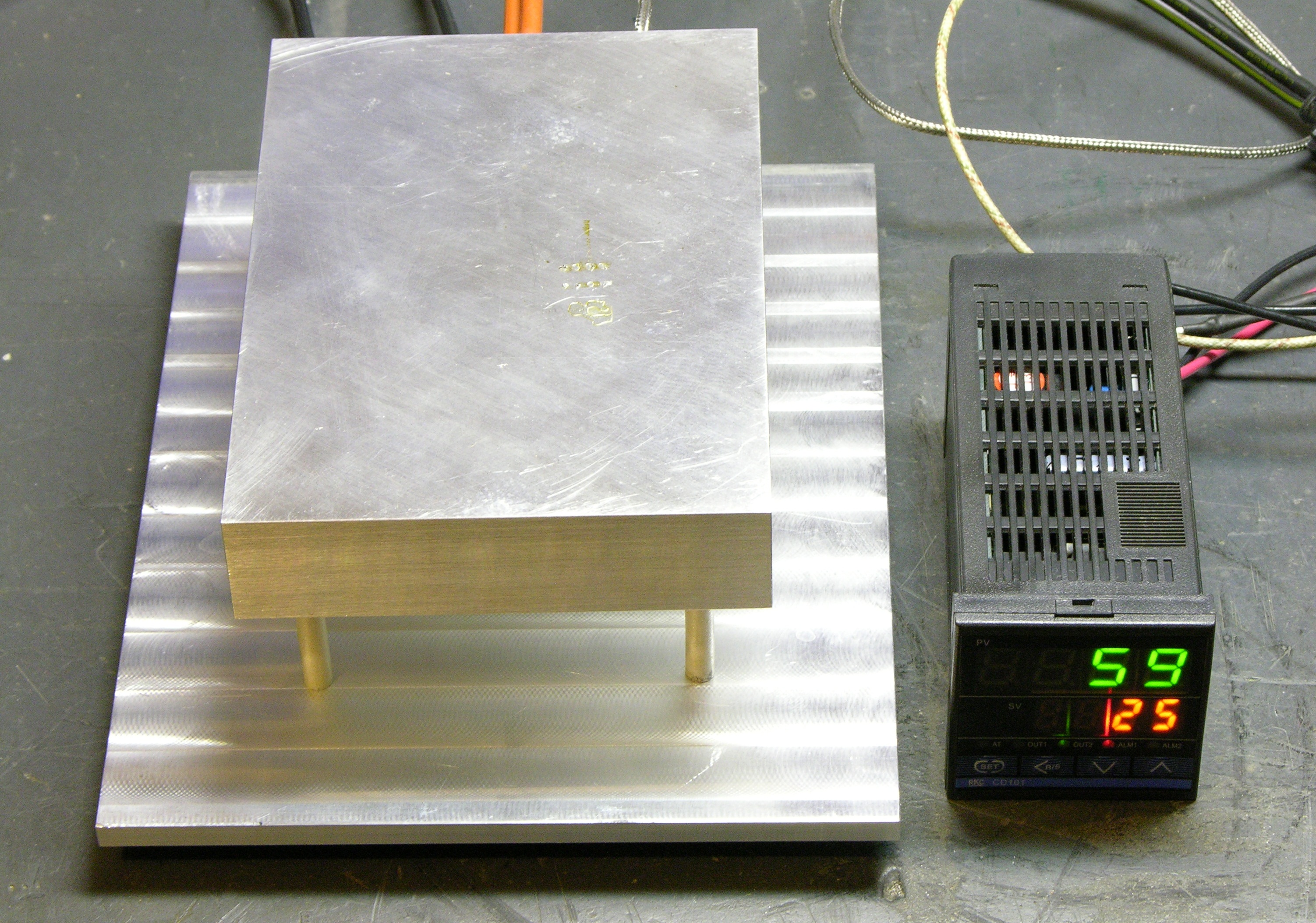
PID-controlled SMT soldering hotplate

So last night I got a working proof-of concept hotplate going, and tonight I can start on the CupCake SMT boards. W00T!

Here’s the tale of how to build a copycat PID-controlled hotplate, with a digression into how lucky I got buying exactly the right PID controller with no idea what I was doing.

Read the rest of this entry »

Makerbot Cupcake Opto Endstops

May 1st, 2009 by Keith Neufeld

I’ve been massively interested in the RepRap project since I first heard of it a few years ago. RepRap — short for replicating rapid-prototyper — is a CNC machine to extrude hot plastic and build up a model additively, like a robot hot-glue gun. It promises to lead the affordable desktop fabrication revolution, printing at home on a sub-$1000 machine what the aviation lab at work printed for me on a $30 000 machine (which itself is already orders of magnitude less expensive than the ones I saw in use when I worked at Cessna Aircraft).

The RepRap can replicate many of its own parts — so once you get one, it’s a matter of feeding it plastic and a few hours (and motors, and circuit boards, and commonly-available hardware) and you can have another one for your friend. It should be pretty viral once it gets going — but getting going is the problem. Even with various “RepStrap” (RepRap bootstrap) designs, the barrier to entry to build my own from scratch was still a bit too high for me — particularly for the heater/extruder nozzle.

So when I saw that Zach “Hoeken” Smith (a member of the RepRap team who’s designed most or all of the current-generation electronics), Bre Pettis (the “talent” on the first Make Magazine videos I remember seeing), and a couple of guys I don’t recognize (sorry, couple of guys!) had teamed up to found MakerBot and were selling the CupCake CNC kit, a complete set of parts to build a RepRap-compatible machine, I was onboard in a heartbeat. The price still feels a bit steep, but the time was right and I got one of 20 presale kits.

It came last week and what with other obligations, I haven’t even had time until last night to start working on it. So I’ll be doing this a slow step at a time; and the first step was assembling the through-hole optical endstop PC boards.
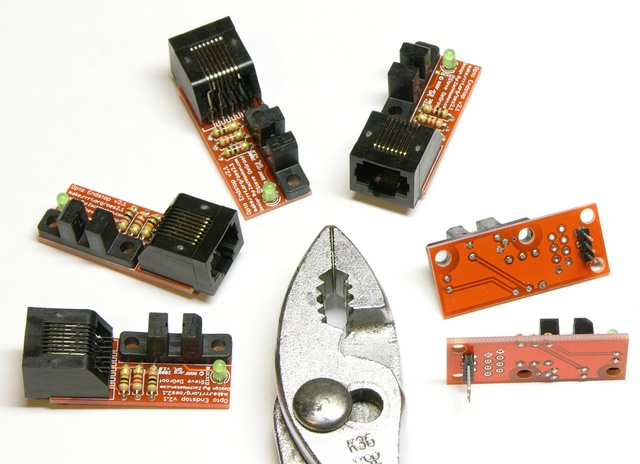
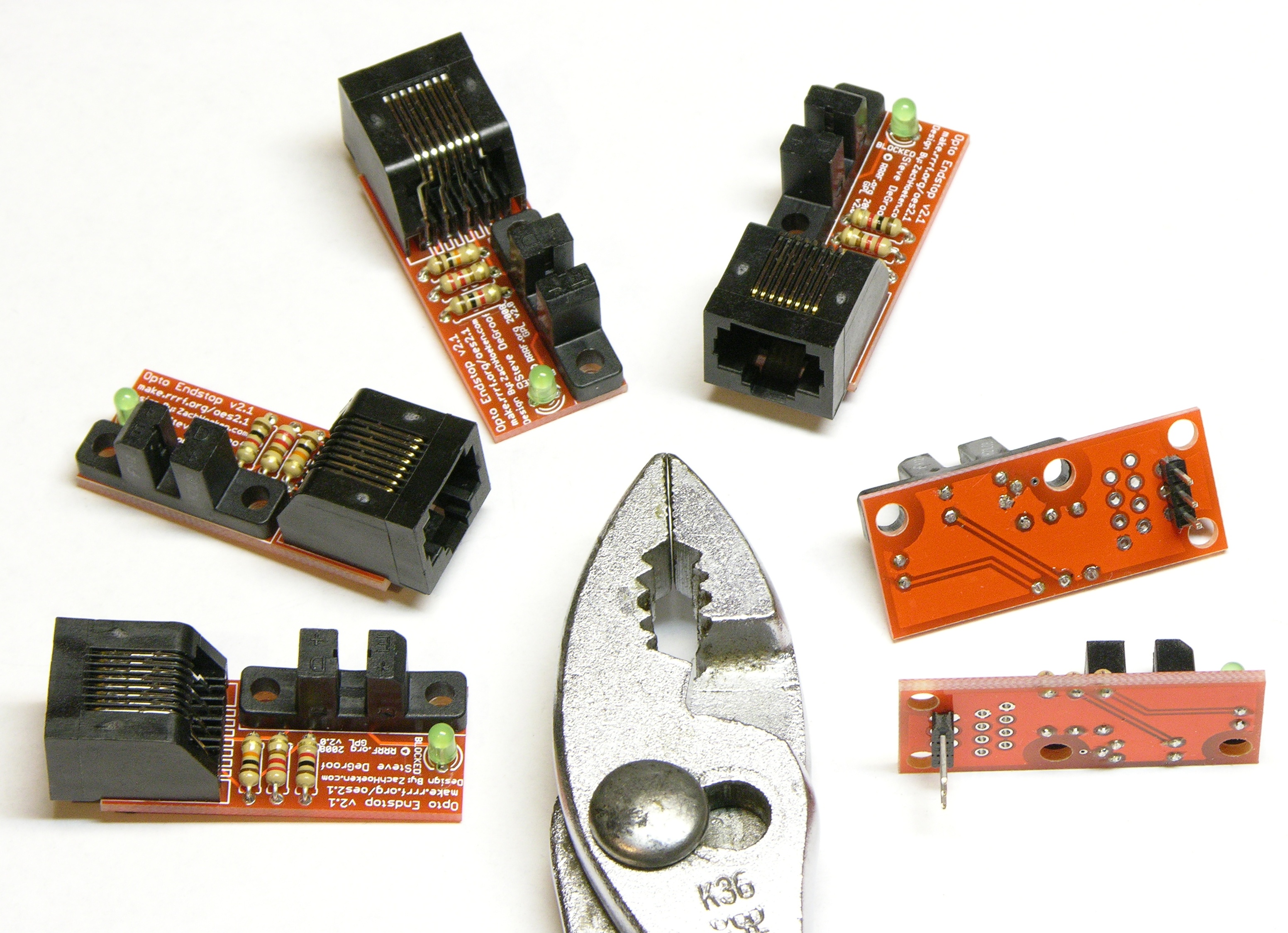
Complete set of Makerbot CupCake opto endstops

The CupCake calls for six endstops — two for each axis — and they use RJ-45 cables for most of the connections, but three-pin headers for the Y axis due to space considerations.

The boards are nicely made; I like it a lot that they’re no larger than they need to be; and I really enjoy the red.
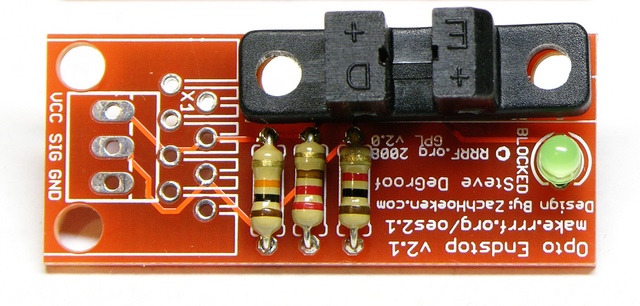
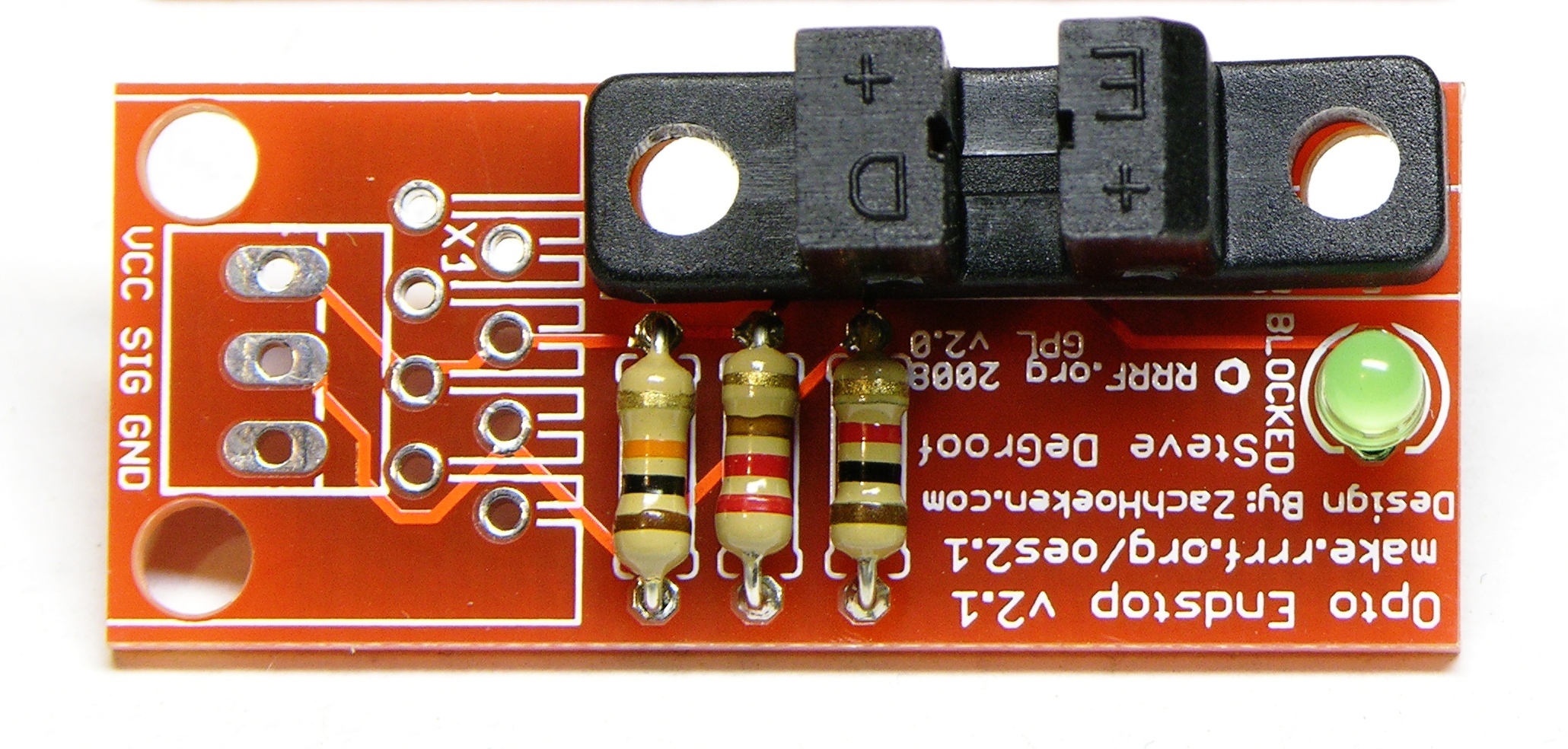
RepRap opto endstop optointerruptor alignment

I have only a couple of cautions for assembling these. First, as noted in the CupCake electronics assembly instructions, the PC board’s optointerruptor footprint is a little off, and it takes some shoving to get the mounting holes aligned. This does matter because these holes are how the board mounts to the chassis, so take the time to get them as close as possible.
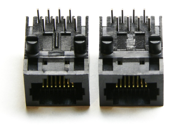
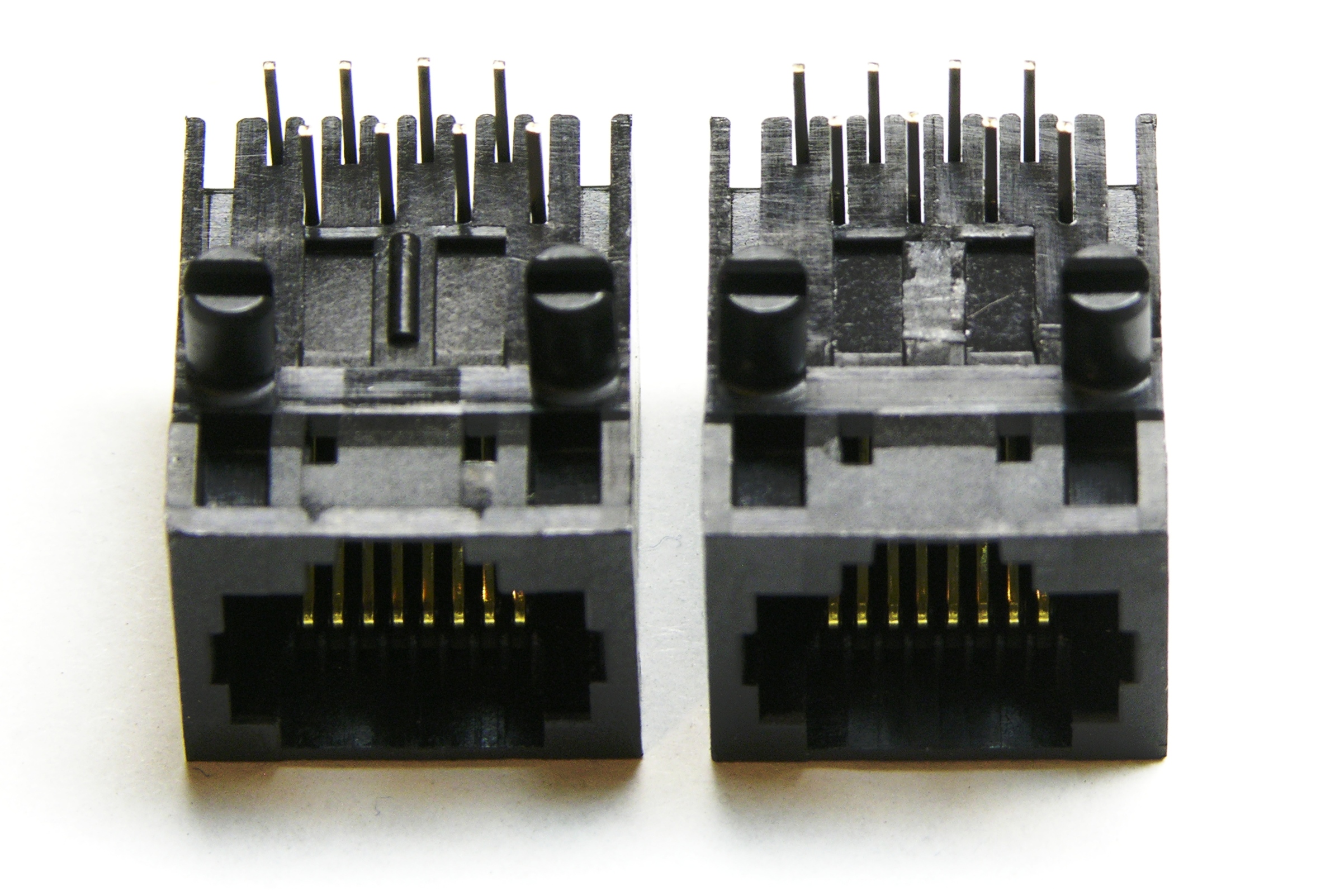
RepRap opto endstop RJ-45 jack modification

Second, use a chisel to shave off that spacer tab on the underside of the RJ-45 jacks. If you don’t, they won’t sit flush, and that bothers me.
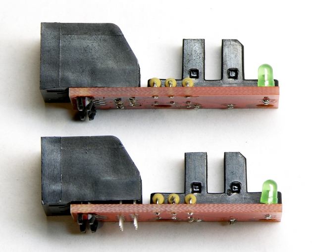
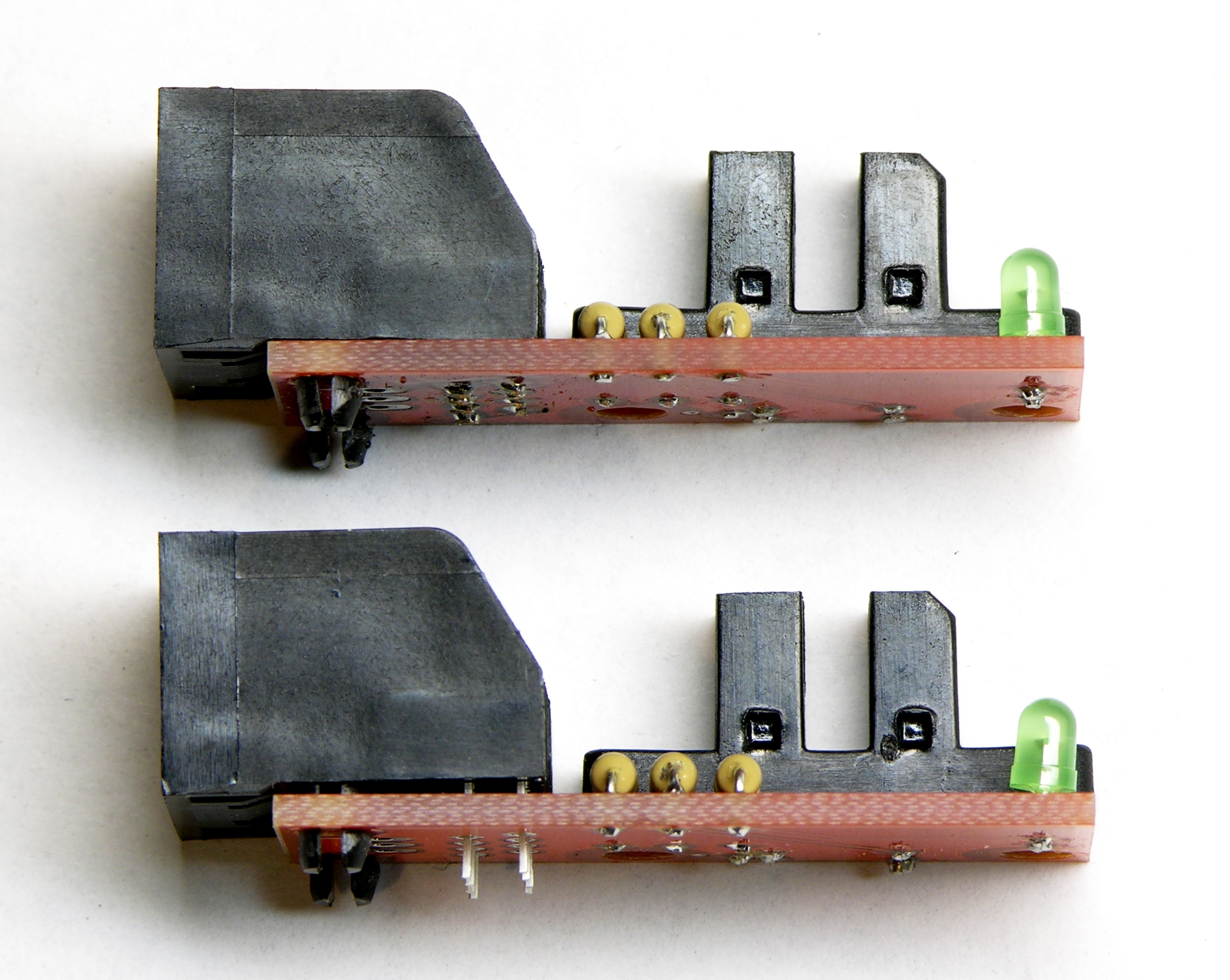
RepRap opto endstop RJ-45 jack fit with and without modification

Take my word for it, it’s way easier to do this before you start soldering the pins.
Refurbishing My Isolation Transformer

April 30th, 2009 by Keith Neufeld

An isolation transformer, as used in electronics testing and repair, is a line-powered transformer with 1:1 windings (e.g. in the US, ~110VAC in, ~110VAC out). It’s used to isolate a circuit under test from line power for two main reasons (that I know of):

  • With line-powered equipment, if you were to touch a hot part of the AC side of the circuit while it was plugged straight into wall power, you could become a return path to ground and get electrocuted.

    The transformer isolates it from the rest of the world, so your risk is reduced to becoming a return path within the circuit, and you’re not at risk of conducting from any single point to ground. This doesn’t eliminate the need for care, but it reduces the hazard.

  • Some line-powered circuits use a local ground that is something other than earth. (The mixer power supply I repaired recently uses a local ground on its primary side that’s at about -85VDC with respect to earth.)

    If you want to use test equipment (oscilloscope, line-powered meter, etc.) to probe the circuit, you need to connect the equipment’s ground to the circuit’s ground. If they’re both line-powered and the circuit uses something other than earth as ground and you connect the equipment’s real-earth-ground to the circuit’s specifically-non-earth-”ground,” you’ll create a short circuit fatal to one or both pieces of equipment.

    The isolation transformer “floats” the circuit so its local ground is safe to connect to your test equipment’s ground. Of course, this potentially reintroduces the shock-to-earth hazard mentioned above, during the time you have the grounds connected for testing.

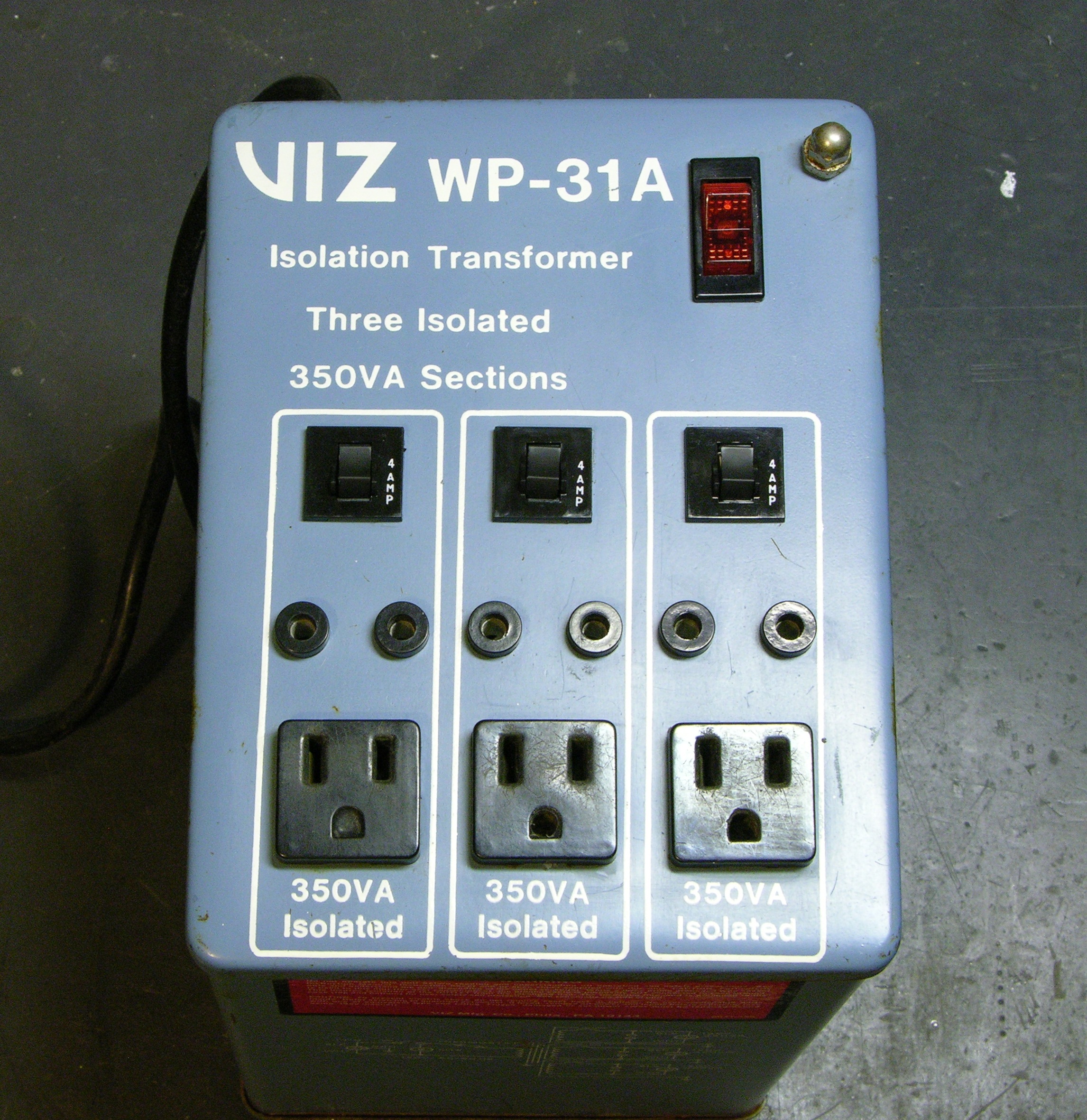
Viz WP-31A isolation transformer with carrying handles removed

While repairing the aforementioned power supply, I dug my isolation transformer out of the basement. I had acquired it grungy and broken (and this is odd, but I don’t remember whether I got it from Slim or purchased it at Lloyd’s) and it had been through a basement flood, so it needed rework before I could use it. I’ve just polished off the last of the repairs.

Read the rest of this entry »

Two Birds

April 27th, 2009 by Keith Neufeld

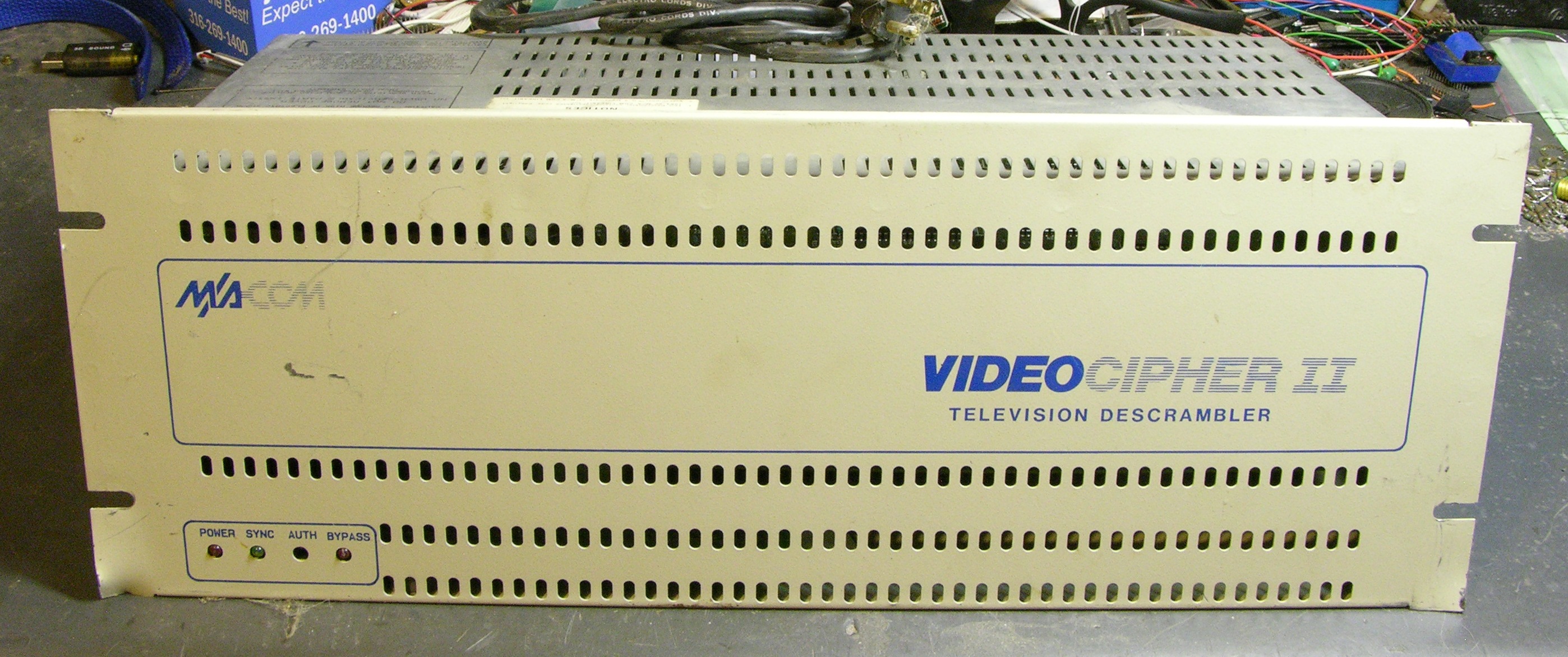
I want to replace the abraded power cord on my brother’s sump pump in exchange for his letting me borrow it. Cort needs four panel-mount BNC connectors for an amateur radio handheld direction finder project. Convergence.

VideoCipher II television descrambler, front

Don’t panic. If for some weird reason you need one of these, I have more where this came from.

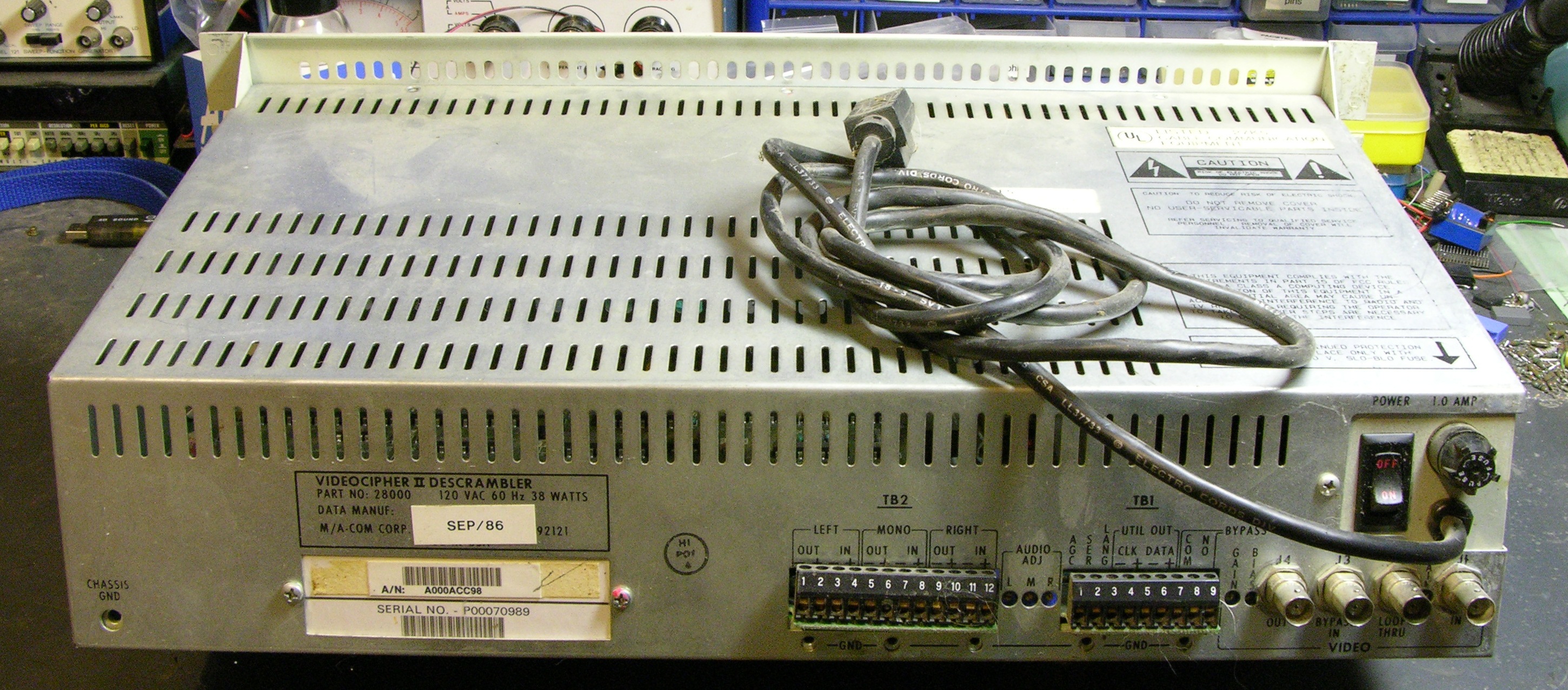
VideoCipher II television descrambler, rear

It’s a little hard to see from these shots, but the case profile is a weird trapezoidal shape.

VideoCipher II television descrambler, interior

Physically large linear power supply; two main PCBs.

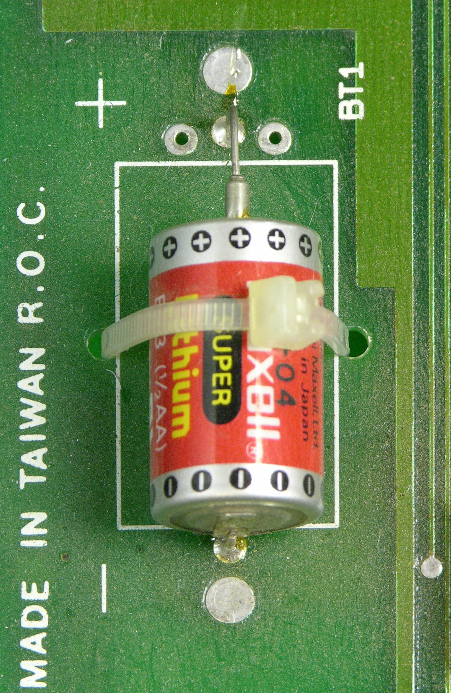
Lithium 1/2 AA cell

Lithium 1/2 AA cell from April of 1989. Rated for 3.6V and still holding 3.69V after twenty years.

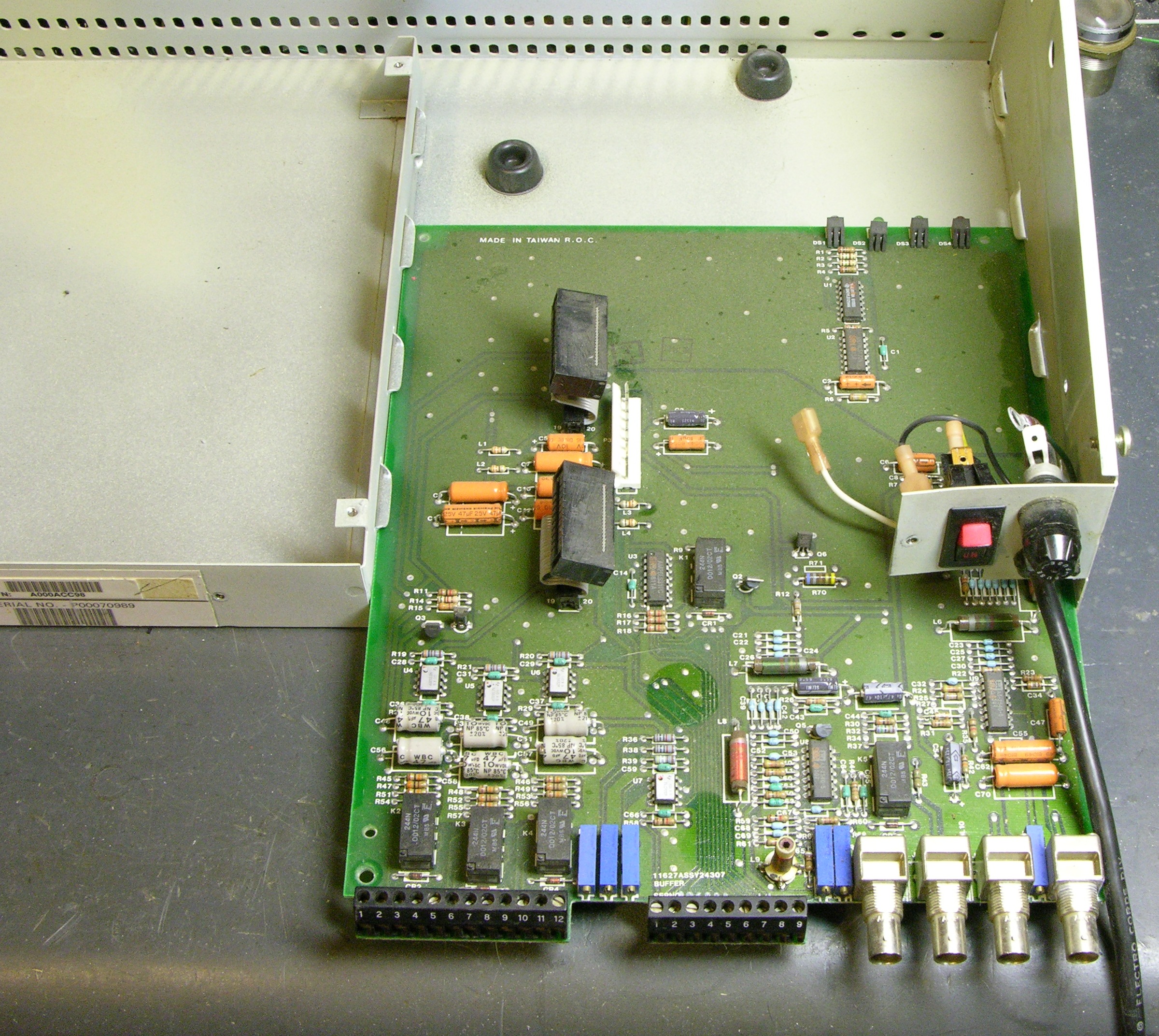
VideoCipher II television descrambler, PCB sliding out

Not sure why they used two PCBs (don’t tell me they really needed the extra 20 square inches), but it’s cute the way this one slides out.

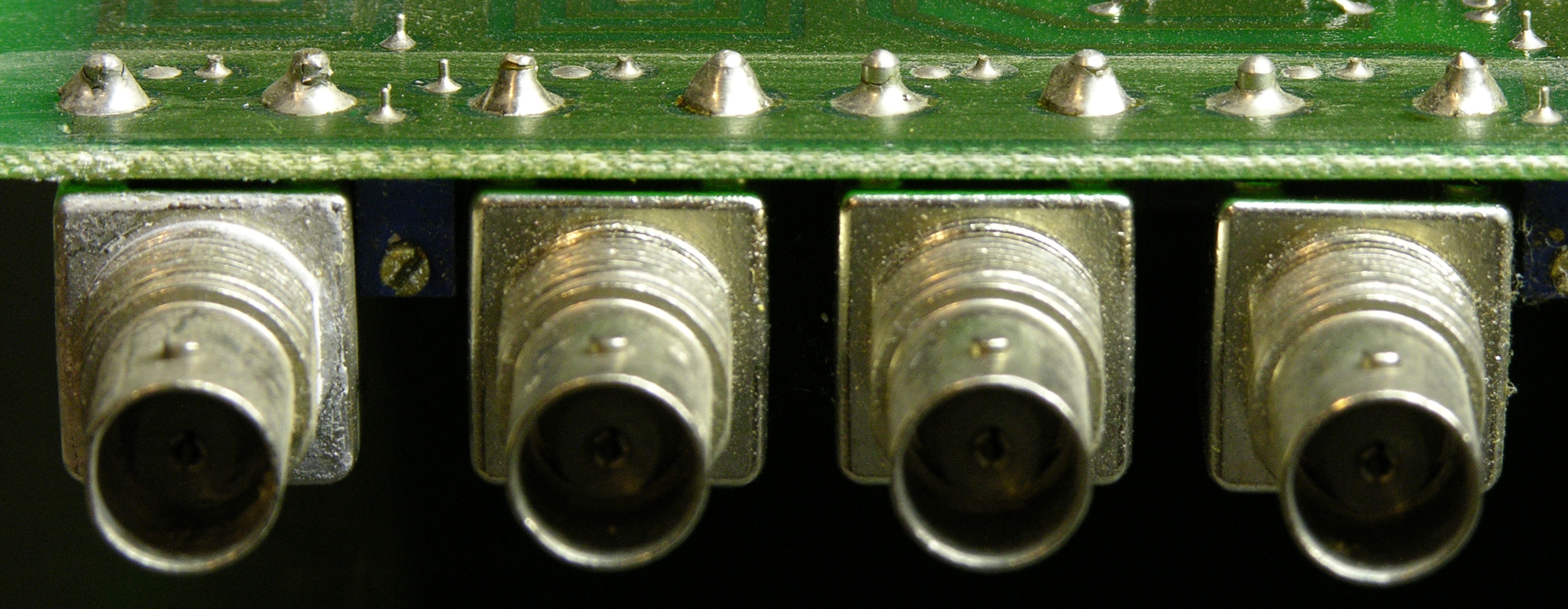
Four PCB- / panel-mount BNC connectors

Every one of these had its shield pins broken free of both solder joints. Looked like cold solder, but I assume it was just mechanical stress.

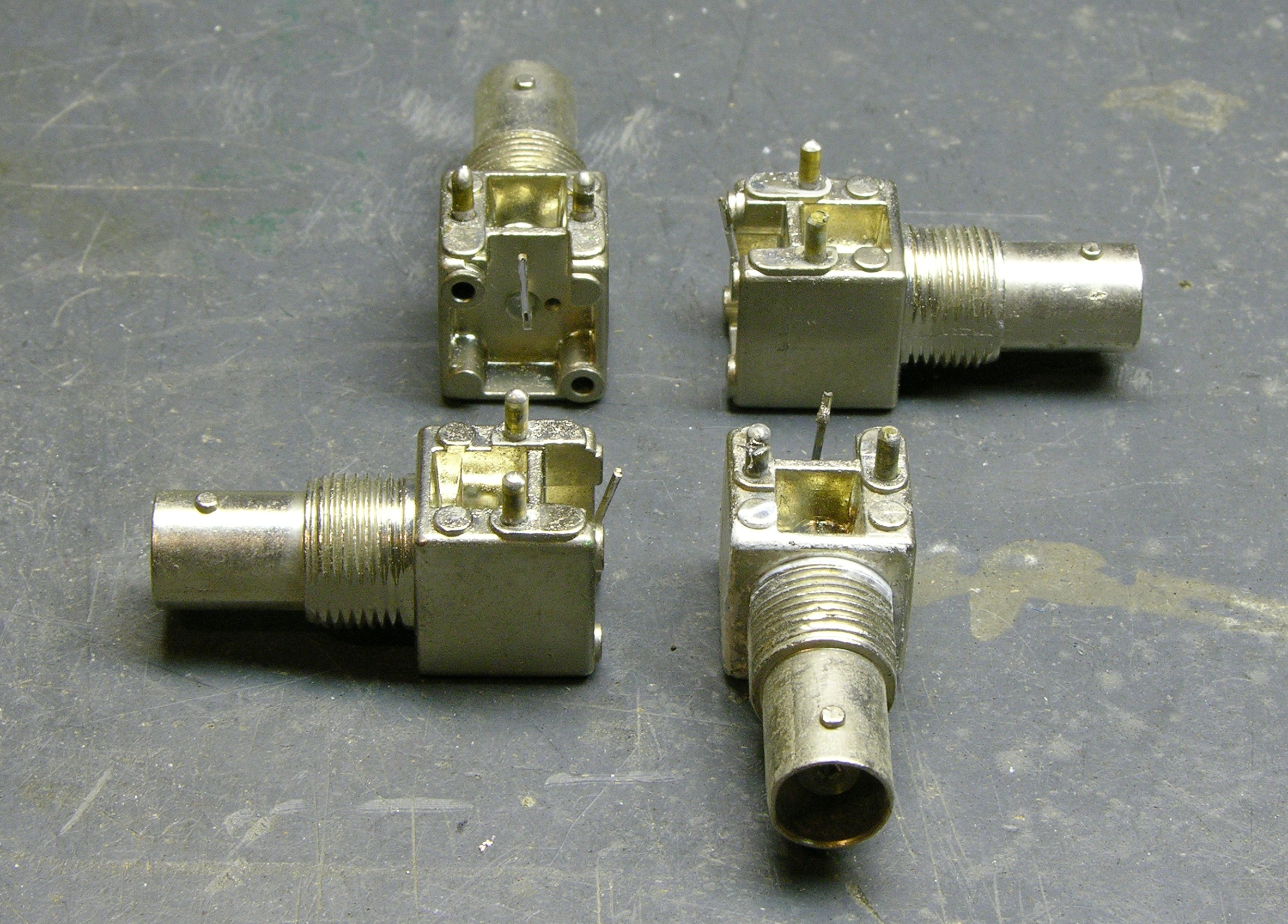
Four PCB- / panel-mount BNC connectors

Voila! Four connectors for Cort. And a power cord for my brother, that I’m out of time to swap onto his pump tonight. Tomorrow, then.

Reducing Kickback Noise in Soundcraft Spirit E6 Mixer Switching Power Supply

April 26th, 2009 by Keith Neufeld

Last weekend, I had repaired a Soundcraft mixer switching power supply, but still had switching noise spikes from the transformer primary showing up on the circuit’s ground, and asked whether anyone could suggest how to reduce them or whether they were an artifact of the way I was using the oscilloscope.

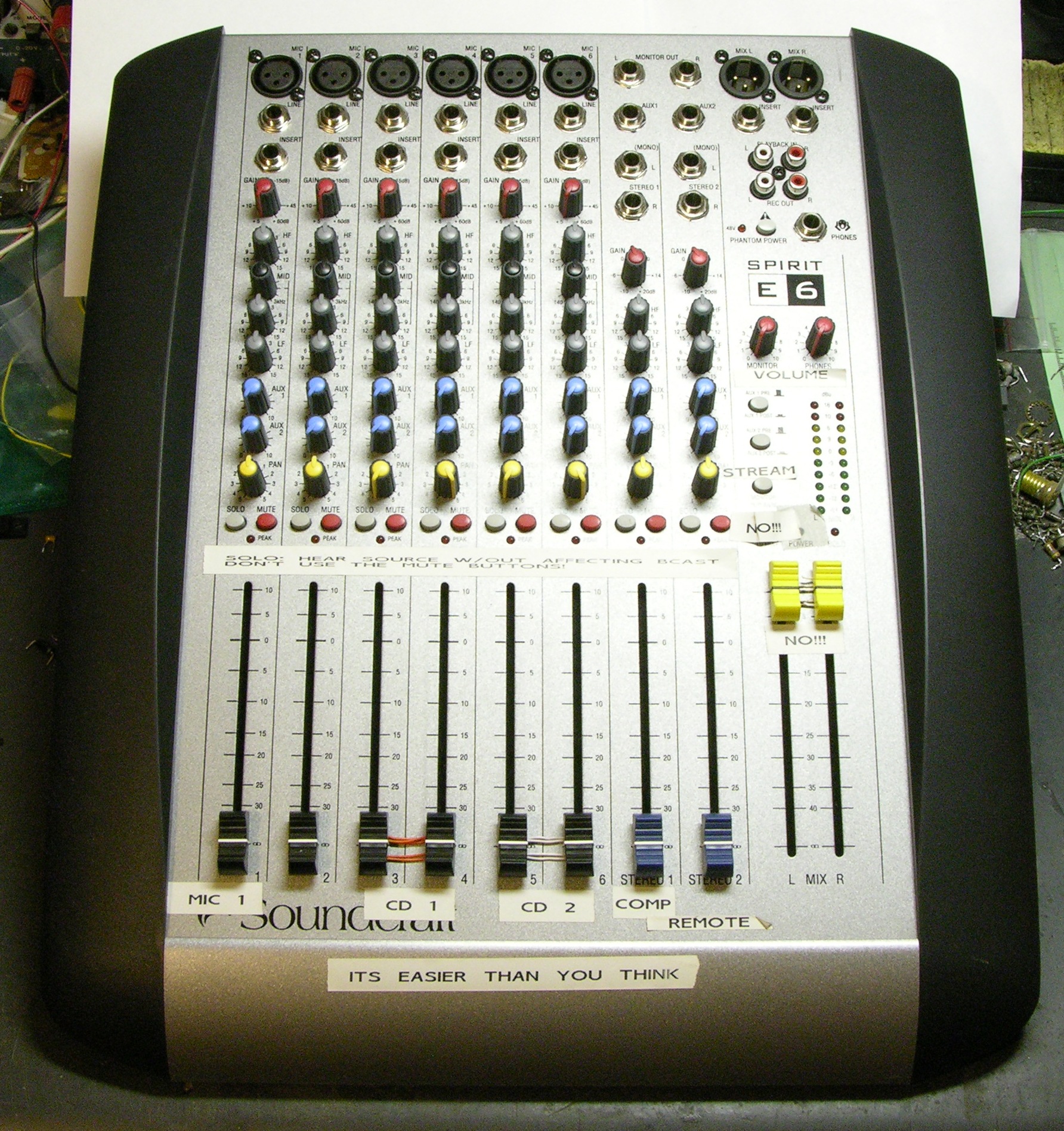
Soundcraft Spirit E6 Audio Mixer

Many thanks to everyone who wrote in with ideas! Because of your suggestions, the mixer is now fixed (enough), back together, and ready to go back to the radio lab.

Here were the ideas and their results:

Read the rest of this entry »

Repairing a Soundcraft Spirit E6 Mixer Switching Power Supply

April 19th, 2009 by Keith Neufeld

A few weeks ago, John mentioned to me that one of the audio mixers in the art and technology / Internet radio station lab had stopped powering on. I said I’d have a look at the power supply and see if I could fix it, and he sent it with me. Turns out we both got a little more than we bargained for — I in terms of effort required and he in terms of time without the mixer.

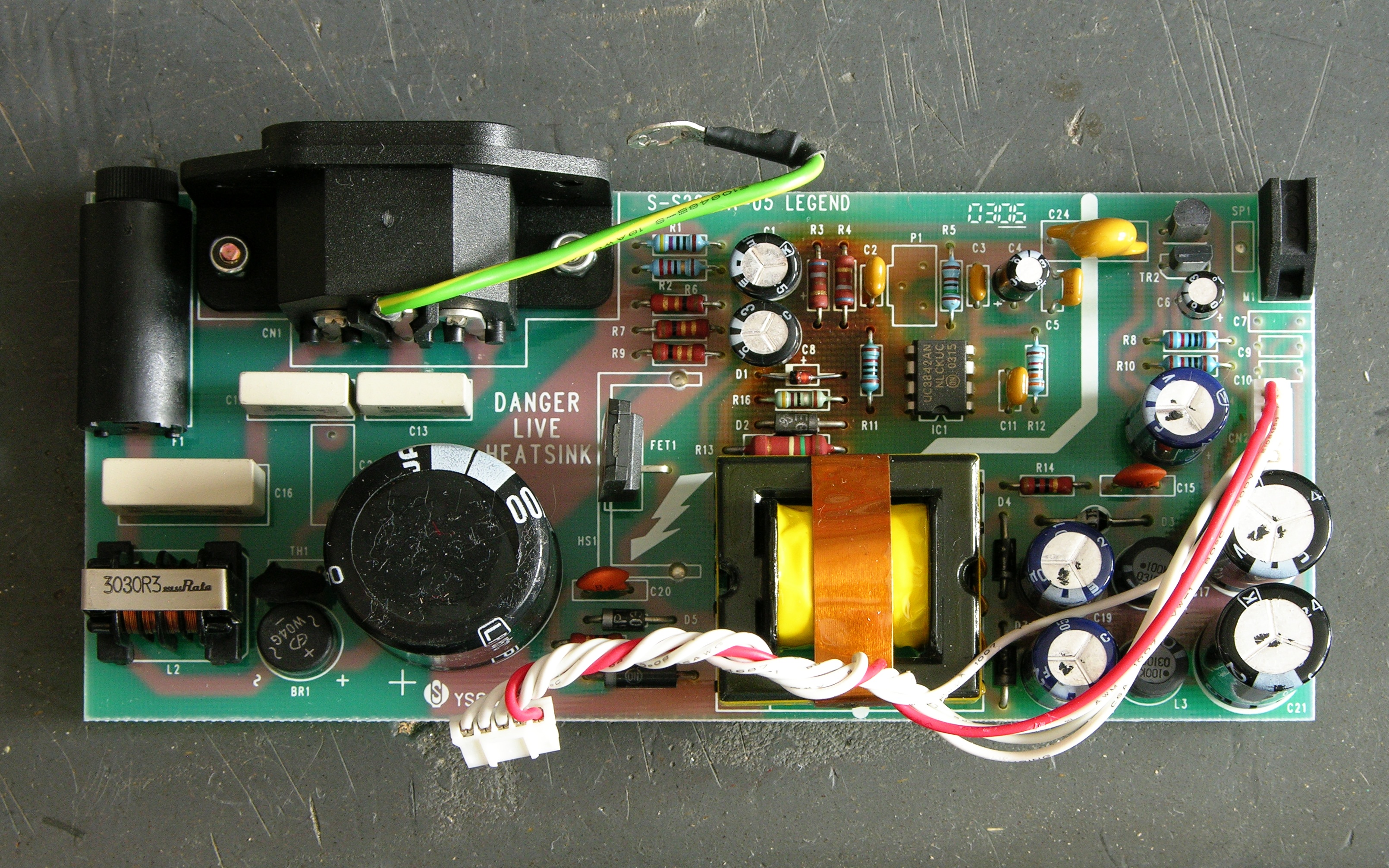
Soundcraft Spirit E6 mixer power supply board

I didn’t know whether it’d be a linear or switching power supply, and it turned out to be switching. I figured it’d just have some baked electrolytic capacitors I could replace, and it turned out that was just the beginning.

I’ve got it mostly fixed now, and it’s been a long and interesting road.

Read the rest of this entry »

DIY Power Injector for Axis 2100 Network Camera, Part I: Investigation

March 24th, 2009 by Keith Neufeld

A little while back I bought a couple of used Axis 2100 network cameras, intending to use them at home (driveway cam? front yard cam?) to replace my lousy Linksys WVC54GC. The Linksys’s video stream is viewable only in Internet Explorer or with VLC; the Axis (although older) streams motion JPEGs that can be viewed with just about anything, provides still JPEGs, and has FTP server upload capabilities to update a statically-served image on a web server.

Axis 2100 network camera

Power Over Ethernet and Power Splitters

Having got them, I decided I’d like to play with one at work, installing it in our 3rd-floor bay window overlooking campus, so those of us with windowless offices can get a little sunshine in our lives. That would be easiest if we didn’t have to run both ethernet and power to the camera separately, so I started reading up on the camera’s power capabilities.

Power over Ethernet (PoE) is a standard for delivering 48VDC over an ethernet cable — depending on the implementation, possibly on the same pairs used for data, possibly on the spare pairs. The data pairs use differential signaling (the difference between TX+ and TX- is the signal, like balanced audio, as opposed to a single signal referenced to ground), so the DC power can be provided on the two wires of one pair and grounded on the two wires of the other pair (similar to the way phantom power is provided on balanced audio cable).

The product web page almost intimates that the camera supports PoE:

  • Access to a power outlet not needed with use of Power over LAN Midspan and Active Splitter from Axis
  • No need for power outlets and electrical cabling using Power over Ethernet products

But in fact the camera doesn’t operate when hooked to a PoE connection. Additionally, another Axis page lists a “PoE splitter” for the camera, which strongly suggests that power may be delivered over the ethernet cable by standards-based or non-standards-based means, but must be split externally before entering the camera.

Axis 2100 network camera, end view

Still, pp 59 and 62 of the users guide show intriguing connections among the I/O port, the power connector, a bridge rectifier, and a switching power supply; and p 65 lists the power supply as accepting 9-15VAC or 9-15VDC, which is kind of interesting. Even though the unit clearly doesn’t function on PoE, I thought it was worth opening up to see whether it would accept non-standards-based power on the ethernet port.

By the way, recognize that green thing?

Going In

Axis 2100 network camera main PCB

Here’s the camera with the bottom of the case lifted off. Note that the top of the circuit board faces the bottom of the enclosure.

Axis 2100 network camera CCD

The CCD is on a separate PCB stuck onto the end of the main board.

Axis 2100 network camera PCBs

Another view of the top side of the board with the CCD board separated.

Axis 2100 network camera main PCB, back side

And the bottom of the board (facing the top of the enclosure).

Continuity

I started by trying to trace connectivity from the power jack to the unit’s ground, not remembering that the camera accepts AC input. I got no continuity there, as my tester doesn’t indicate continuity through diodes. After noticing the bridge rectifier (last photo above, just to the left of the upper right corner), I realized my error and was able to trace ground from the rectifier output throughout the unit.

Next I traced from the power jack to the I/O connector and confirmed the connections shown in the user guide — you can provide or draw rectified and filtered but unregulated DC power on the I/O connector.

Feeling bold from my discoveries, I checked continuity to the ethernet jack. I got DC continuity between ground and the center pins 4-5, but no other connectivity. Bah! No non-standards power on ethernet for me.

Hm, but I also hadn’t successfully traced V+ from the rectifier throughout the unit. I figured I needed to pick it up from the other side of the LM2596 voltage regulator — which turned out to be a switching step-down regulator.

LM2596

Pin 4 is the feedback that connects to the filtered, regulated output — and indeed, it connects to the V+ power supply pins of all kinds of things throughout the circuit. Cool; progress! Maybe the regulated DC voltage connects to the ethernet jack???

Mm hm, it sure does. I get DC continuity with .4-.5Ω resistance from the V+ rail to ethernet pins 1 and 2 (TX+ and TX-), DC continuity with .2Ω resistance to pin 3 (RX+), and no connection to any other pin.

So?

Although the datasheet’s application circuit above shows the 5V step-down regulator, the camera actually uses the LM2596S-3.3 for 3.3V power. That this appears on both TX pins of the ethernet port suggests that I could provide DC power on pins 1-2 and ground on 4-5.

But it would have to be regulated 3.3VDC, which (1) isn’t standards-based PoE and (2) isn’t going to travel well over 100+’ of cable. This suggests that a non-standards-based switch-end power injector directly in through the camera’s ethernet isn’t going to work well.

More plausible: Build a PoE-attached power supply with a 48V-3.3V step-down converter and hang it off the back of the camera. At first I thought that doing PoE would require a dedicated PoE chip to do the negotiation, but all that’s needed is a 25kΩ resistor across the powered pairs. So it really would be feasible to do, without a special chip just for the PoE.

However, if the solution is going to require external PoE down-conversion anyway, why bother going all the way down to the regulated 3.3V? Why not go 48V-12V and come in the regular power jack, which also eliminates any risk of making the LM2596 unhappy by feeding power into its output? (Its block diagram looks like that shouldn’t be a problem, but I don’t know enough to be certain.)

If using an external down-converter anyway, the only drawback I can see of splitting the power out to feed the the power jack separately rather than the ethernet is the requirement for an extra connector.

Or the Simple Way

Regardless, I don’t really want to have to build an external step-down regulator just to get the cameras working. So for now, I’m more likely to build simple cable splitters to inject 12V onto unused pairs at the switch end and split it out to the power jack at the camera end.