Archive for the ‘Inside’ Category

Salvaging a Pile of VCRs

Monday, November 10th, 2008

VCR mechanics, PCB, and wiring harnesses

A few weeks ago, I tore into a stack of dead VCRs, salvaging interesting parts, recycling a lot of metal and plastic, and intending to reduce the volume they consumed. Unfortunately, the resulting lesser volume has been mounded up on my workbench instead of neatly stacked in the garage.

The insides of VCRs are familiar to most tinkerers, but some of the bits are more interesting in bulk.

(more…)

(Ancient) Disk Drive Heads

Monday, October 6th, 2008

Lawrence’s son Jacob has been cleaning out their basement, and recently dismantled a TI disk drive about half the size of a washing machine — the kind where you load big cylindrical disk packs down into the center. They gave me a bunch of circuits from it to recycle, and I was intrigued by the disk heads.

TI disk drive heads

I grabbed them at first for the .1″ header connectors, and I was tickled by the spring armor around the wires, and then I decided I just liked the whole things.

TI disk drive heads, closeup

Enough to take a few pictures, anyway. But now I think it’s time to keep the wiring harnesses and ditch the rest.

Heh — if I got TGIMBOEJ, I’d throw some of these in. :-)

Interesting Bits of Old Motherboards

Monday, September 1st, 2008

I’m salvaging parts from some very old, dead (leaking capacitors and batteries, corroded components) PC motherboards and found some interesting bits.

ICs inside IC socket

14-pin ICs mounted inside a 40-pin IC socket (that was populated). Very cute. Makes me want to do something extra-naughty, like mount an SMT IC underneath a DIP (no socket needed).

18/20-pin IC sockets

18/20-pin IC sockets, so you could pick which size L2 cache chips to install. Although it’s not obvious from straight above, these are not hacked together out of regular sockets — they were manufactured this way.

I found them on two different vendors’ boards, and I had never noticed them when I was servicing PCs during that era. I guess it solves the problem of knowing which end of a regular 20-pin socket to stuff an 18-pin IC in; or maybe the 18-pin and 20-pin ICs didn’t have compatible pinouts.

Novell 8088 motherboard with onboard ethernet

A Novell 8088 motherboard with onboard ethernet. Various other curiosities are visible in the large version of the picture, but worth noting is the “PC TERM. BIOS,” which leads Joel to question whether this was a dual-function PC and network terminal.

Swell Pedal from Baldwin Model 5 Organ

Thursday, July 3rd, 2008

July 7, 2008

Welcome, MAKE: Blog readers!

Whoever posted this to the MAKE: Blog jumped the gun a bit — I haven’t interfaced anything to a synthesizer yet. What I found in the Baldwin pedal isn’t suitable for interfacing and is (in my opinion) worthy of preservation, so this post is just a teardown of the Baldwin pedal showing the intriguing mechanism inside.

I have since gathered all the parts I’m going to use to build the MIDI volume/expression pedal and expect to do that within a few days; so if you’re interested, please check back!


I want to build a volume pedal for my synthesizer(s), and I figured it’d be easier to do if I started with . .  a volume pedal. So last night I went to storage and pulled the swell pedal out of Jacob’s most recently discarded electric organ, a Baldwin Model 5.

Baldwin Model 5 organ swell pedal, front view

It’s actually quite a bit higher off the floor and more steeply angled than would really suit me; but I had it on hand and figured I might as well start working with it. As it turns out, I’m not going to retrofit this, and I’ll show you why in a little bit.

Baldwin Model 5 organ swell pedal, mechanism

Rocking the pedal forward pushes the square lever away from the box, and rocking it back pushes the lever toward the box and presses a pin at the base of the lever into the box.

Baldwin Model 5 organ swell pedal, electronics enclosure

The lever and box assembly looks kind of like a giant microswitch. Or a bird with a long neck.

Baldwin Model 5 organ swell pedal, electronics mechanism

Here’s the part that makes me say, “Wow.” Apparently potentiometers hadn’t been invented yet (I think I’m joking), or weren’t available with a high enough power rating to use in this volume control circuit.

The volume pedal’s lever presses against a ladder of leaf switches (it’s hard to see, but all the contacts at the left end of the leaves are normally open, but only barely) wired to a resistor ladder. Pressing the pedal connects together increasing numbers of leaves and shorts across increasing numbers of resistors. Wow, wow, wow.

I just don’t feel right about dismantling this to stick in a potentiometer (nor are the mechanics of it really built to make that easy).

So now I’m looking for another swell pedal (with a pot) to repurpose, ideally a twin swell pedal like what’s on Jacob’s current organ. I don’t find much on eBay, and I’m not sure where else to look.

Parting Out an Optoma EzPro 610H Projector

Monday, May 5th, 2008

I just disassembled a dead Optoma EzPro 610H projector from Jeremy, to look for a polarizing filter to fix my InFocus LP290 and see if Marsh Ray can fix a Sony VPL-PX15. The filters from the Optoma look to be about the right size for my InFocus, so I’m excited to think I may be able to get it working again 100%.

Meanwhile, I ended up with a whole bunch of parts I don’t need, some of which might be useful for repairing other EzPro projectors. I’d like to offer these to anyone who could use them, for whatever you think they’re worth plus the cost of shipping. If you’re interested in any of these, see below for instructions.


Update 06-May

Jeremy says:

Had power indicator lights, but bulb would not light. Replaced bulb, same deal.

So the problem is likely in one of the logic boards (microprocessor not responding to sensors that say it’s okay to power up the lamp) or power supply boards.


Available Parts

Projector lamp

Projector lamp. Sold. I don’t know whether it works, I don’t know how many hours of use it has, and I don’t have any way to test it. I believe lamp failure is not what killed the projector.

Projector lamp power supply

Lamp power supply. I don’t know whether it’s good and I don’t have any way to test it; but it’s modular enough, if you suspect it’s what’s wrong with your projector, it’s worth trying.

Interlock switch

Lamp service panel interlock switch. Not very exciting . . . but handy if, um, mice have been living inside your projector.

Three projector cooling fans

Three cooling fans that mounted to the optical housing: rear left, right, and bottom.

Two projector cooling fans

Two cooling fans that mounted to the case: bottom and front.

Projector input panel

Video input panel and associated PCBs.

Projector control panel

Top control panel and attached PCB.

Projector LCD panels

All three LCDs are available, removed from the prismatic lens thinger on the left and without polarizing filters. I removed the red LCD (right) from its mounting frame (further disassembled than it is here) before I found where the polarizing filter was (elsewhere), so it needs some RTV reapplied to hold it firmly in its frame. This will be obvious upon inspection.

Projector book, handle, and remote control

Owner’s manual. Sold. Carrying handle. Remote control that looks slightly different than what’s in the book but has the same part number. Sold.

NOT Available Parts

I’m NOT giving out the following, so don’t even ask:

  • Any of the optics. I think they’re unlikely to be damaged in anyone else’s projector, I think they’d be difficult to replace and realign successfully if they were damaged, and I think they’re kinda cool to hang onto.
  • The projector’s main board and main power supply board. I think they’re too likely to have been the source of the problem with this projector, and I’m just going to harvest them for components.
  • The last polarizing filter. I’m going to hang onto it for a rainy day.

How to Make a Request

If you’re interested in anything from here, post a comment below indicating what you want, what it’s worth to you, and what your ZIP code is. Make sure you enter your email address correctly on the comment form, because that’s how I’m going to contact you.

Then add my email address, neufeld at this domain, to your address book or whitelist. Because I have an unusual domain name and because I run my own email server, a lot of email from me ends up in people’s spam folders. I will only email you once. If you want something from me, make sure you receive that email.

I’ll contact you shortly to let you know whether I still have the item, and how much shipping will cost. You PayPal me the cost of shipping only, and I’ll send you the item. When you get it, if it works, you PayPal me whatever you think it’s worth. If it doesn’t work, you send it back at your expense and I’ll add it to my junk pile.

Rotary Encoder from a VW Car Stereo

Sunday, May 4th, 2008

or

A Well-Stocked Junk Bin is the Mother of Having Everything You Need


July 7, 2008

Welcome, MAKE: Blog readers!

Whoever posted this to the MAKE: Blog missed what I think is the more interesting accomplishment — over the weekend, I put (most of) the polishing touches on an Arduino library to read multiple quadrature encoders reliably in an interrupt service routine, instantiating them as objects so they’re extremely easy to use with essentially no code.

You are of course welcome to read here about the rotary quadrature encoder itself; then if you’re interested, head to LED Calculator with Rotary Quadrature Encoder for Target System Voltage Selection for the Arduino library.


After the tragic disappointment of finding that my salvaged printer rotary encoder was optical (and I didn’t feel like dealing with the optoreflector circuitry), I mourned for a day, then got over my bad self and thought about what else uses rotary encoders.

Some recent stereos do, especially ugly boom boxes and (non-ugly) car stereos, typically for the digital tuner knob that can rotate forever and ever. And fortunately, I have some of each in the junk bin.

VW Car Stereo

VW car stereo front panel

Here’s the front panel of a VW car stereo from Cort. If I recall the story correctly, it broke when their Jetta had a loose ground in the electrical system and everything went wacky. In any case, they replaced the stereo and gave me the old one. And thank goodness for that, because it has two lovely rotary encoders!

VW car stereo front panel, back side

Here’s the circuit board side of the front panel. If you link to the large version of the picture, you’ll see something that really impressed me: The screws holding the PCB to the bezel are labeled “START,” 1 – 11, and “END,” with arrows pointing from each one to the next, presumably in torque order. Geez, you’d think these guys designed car parts, or something!

VW car stereo front panel, bezel and rubber buttons removed

Here’s the front side of the PCB with the bezel and rubber buttons removed. On the large version of this picture, you can see that every front-panel button has two landing pads on the PCB, one on each end of the button. I’m developing some serious admiration for whoever designed this thing.

Rotary encoder on circuit board

And at last, the object of my obsession.

A few minutes with the soldering iron and I had it extracted. It has two pins on the upper edge for the NO pushbutton action of the switch, and three pins on the lower edge for the common and quadrature connections.

Quadrature Encoding

In the context of rotary sensors, quadrature encoding is the concept that two sensors are measuring the rotation of the same shaft, probably many events per revolution, but 90° out of phase from each other. Here the 90° refers to the staggering of the sensors’ output, not to 90° of rotation of the whole shaft.

As shown in this diagram from the Wikipedia article on rotary encoders, when you rotate the shaft one direction, the first output goes high, then the second goes high, then the first goes low, then the second goes low, etc. Rotating the shaft in the opposite direction causes the events to happen in reverse order. (This is the same scheme as driving a bipolar stepper motor, only sensing rotation rather than causing it.)

Quadrature encoding diagram from Wikipedia

The combination of three pieces of information — which sensor changed state, which way it changed state, and what state the other sensor is in — is enough to determine the direction of rotation. And the period of successive changes in the same direction is enough to determine the rate of rotation (if you care). In my case, I’m going to want to know both — but more on that when I get this wired into the LED calculator.

Decoding My Rotary Encoder

This rotary encoder has detents, or “clicks” as you turn it, and I expected that one of the three quadrature pins would be common and the other two would alternate rising and falling as I turned the knob from detent to detent. In fact, I quickly discovered with my continuity meter that all three are connected together at one detent:

Rotary encoder, two LEDs on

And none are connected at the next:

Rotary encoder, two LEDs off

It turns out that the in-between transitions — 1 to 2 and 3 to 4 in the diagram above — happen between detents. That was hard to check for sure with the continuity checker and only two hands, which is why I breadboarded this.

Rotary encoder, one LED on

It’s much easier to turn to “tween” positions when it’s on the breadboard, and very easy to observe the quadrature output, which does indeed happen with the center pin common and the outer pins alternating.

And it turns out that having an extra quadrature state change between clicks is absolutely perfect for my planned application, because I want to know at each detent how fast the knob was just turned, even if it’s been untouched for a long time and only turned a single click. Having the “tween” transition gives me two transitions per detent, enough to measure rotational speed even for a one-click turn out of the blue.

More tomorrow on why I care about that, if it isn’t already obvious.

Inside an AMT Accel-500 Spinny Wheel

Thursday, May 1st, 2008

At my first “real” job, among other things, I maintained a fleet of AMT Accel-500 wide-carriage printers. Thus it was that in 1990 I was introduced to my first “spinny wheel” user interface.

AMT Accel-500 printer control panel

The printers had a wide range of configuration options, from serial port settings to fonts to paper-advance behavior. All were controlled through this panel, by entering configuration mode, spinning the wheel to select an option, entering change mode, and spinning the wheel to select the value.

As much as I hated certain things about the printers (particularly their declining paper-feed reliability as they aged), I was absolutely enamored of their user interface. For that and other reasons, when my employer finally converted all office printing to laser and retired all the Accel impact printers, I took them home. Thirty-plus of them. Stacked them in two tall stacks in storage, where they still sit.

It’s from those printers that I got the stepper motors I’m using in my CNC project, and I’ve recently cannibalized one for other potential CNC parts. But for whatever reason, although I’ve dreamed over the years of using the spinny wheels in my own user interfaces (custom car MP3 player, etc.), I’ve never opened one to see what was inside. Until tonight.

I’ve received my smaller LCD screens and I’m back to work on the LED calculator, with everything pretty much settled except the means of selecting target circuit voltage. I’d really like to use a rotary encoder, and I’ve found a couple of choices that I can order from Digi-Key; but I really wanted to prototype one tonight. Thus at last I turned to my trusty printer’s control panel, hoping to find a smooth-as-silk mechanical rotary encoder underneath that lovely, lovely wheel.

Feh.

AMT Accel-500 printer control panel, interior

It’s optical, with alternating silver and black sectors on the back side of the disk, and optoreflectors that tuck into recesses in the wheel’s housing.

Bleah, bleah, bleah. I definitely don’t want to deal with optoreflector interfacing tonight, and I really didn’t want to in my hypothetical other projects either. Furthermore, the housing is pretty custom to the wheel and would have to be duplicated or Frankensteined into another enclosure (“Frankenclosure”?), rather than just popping the wheel onto a rotary encoder’s shaft outside the case.

Dear me.

Repairing Alesis M1 Active mk2 Monitor Speakers

Wednesday, April 30th, 2008

For Friday’s show, we used Alesis monitor speakers that we had in the lab, plus Steve, one of the students, supplied two.

Alesis M1 Active mk2 speakers

During installation, one of the speakers started winking its blue power light and ceased playing sound, and before the show another did as well. Steve found a Studio Central forum post suggesting that the problem was due to a failed electrolytic capacitor that gets baked by a hot resistor right next to it, and a quick peek inside confirmed that it was a likely explanation and fix.

Alesis M1 Active mk2 speaker, circuit boards and interior

After unscrewing, the back panel lifts out and reveals the power supply board mounted vertically on a metal shield, and the crossover/amplifier board mounted flat on the panel.

Alesis M1 Active mk2 speaker power supply board

The naughty capacitor, C8 (actually its replacement after I finished), is in the center red rectangle next to the offending resistor. Another bad electrolytic capacitor whose number I forgot to catch is featured near the top of the board. Both of these tested bad with my Capacitor Wizard in-circuit equivalent series resistance (ESR) tester; all of the other electrolytics on the board tested good.

It was simple work to remove and replace the two capacitors on each board, and it brought both speakers back to life. Thank you, forum posts and Capacitor Wizard!

BTW, are electrolytics supposed to look like this?

Leaky electrolytic capacitor

Two caveats about this repair. First, I should have used 105°C capacitors, but I could only find 85°C caps on short notice, so these will fail quickly and need to be replaced again. At least now it’s known exactly what needs to be done. And second, the forum post suggests moving either the resistor or capacitor to get them further apart, which is a great idea but which I haven’t done yet. I’ve been trying to think up a clever way to stick a little heatsink on a vertically-mounted resistor, which might be a better solution yet.

Inside an Airport Extreme Card

Thursday, March 6th, 2008

I’m piecing together a wireless notebook computer for my wife (her first!), and so far it comprises an iBook from Cort with a crashed hard drive, a Toshiba drive from Jeremy, and a refurbished Airport Extreme card from Apple. Silly eBayers take note: You can get the card straight from Apple for only $29 plus shipping; and the shipping from Apple is only $4, not $9.99.

Cort had cannibalized the Airport card out of the iBook to trade for a dead card in another machine, so the iBook came without any wireless. Jeremy had a dead Airport card that he offered me, and I figured I’d at least see whether I could revive it. It didn’t even show up in System Profiler, so I didn’t expect much likelihood of success, but it was worth a quick look for loose connections.

It turns out I was extremely unlikely to have been able to find anything that I could fix, and indeed I didn’t, so I ordered the refurb card tonight. But since I can’t find any pictures online of the inside of an Airport Extreme card, I thought I might as well post what I took.

The top and bottom plates of the card are spot-welded together along the edges, so the first step was filing out the welds with a rat-tail file. After that, there were still some tabs to pry out before it could be opened, but they were fairly easy.

And that’s what there is. Nothing in there really subject to stress from normal use or jostling. I looked it over with a magnifying glass anyway, but nothing leaped out at me. I’m guessing the Broadcom chip bit the dust, for no reason I’ll ever know.

I’m fascinated by the tiny capacitors. I measured them at about 20 x 40 mils, which makes them 0402 packages.

The caps on the back side are even smaller (and harder to measure accurately). I came up with about 10 x about 20 mils, which is 0201. Good lands, those are small.

Now I want an excuse to try to solder one. ;-)

Repairing an InFocus LP290 Projector, Part 1

Sunday, January 13th, 2008

A few months ago, I bought an InFocus video projector on eBay, still hoping to watch movies on the wall of the family room. It’s about 1/12 the size of the behemoth Sony projector I was trying to repair earlier, and quite a bit sharper and brighter; so if I can get it going, it’ll be a nice replacement.

When I received it, I immediately noted two problems: It shuts itself off after anywhere from seconds to hours; and it has a yellow silhouette running up the middle of the picture, kind of like the face/vase illusion.

I’ve taken some time this afternoon to disassemble and diagnose the projector; so although it’s not fixed yet, here’s what I know so far.

Chasing the Yellow Blob

In which Keith removes Crusty Gummy and washes a filter carrier

From the looks of it, I was pretty sure that the blob was going to be something wrong with, or wrong on the surface of, one of the lenses, mirrors, or filters. Yes, it looked a little like an LCD ruined by being left in a freezing car overnight, but not quite. So I dug in to follow the light path through the projector and see if it would be apparent what was wrong.

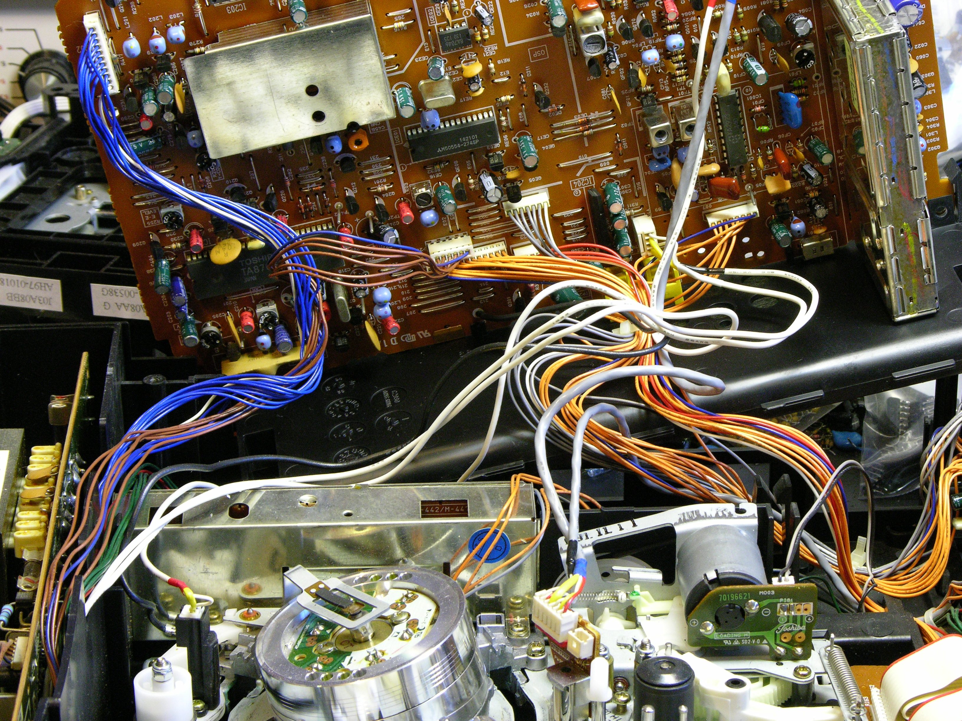
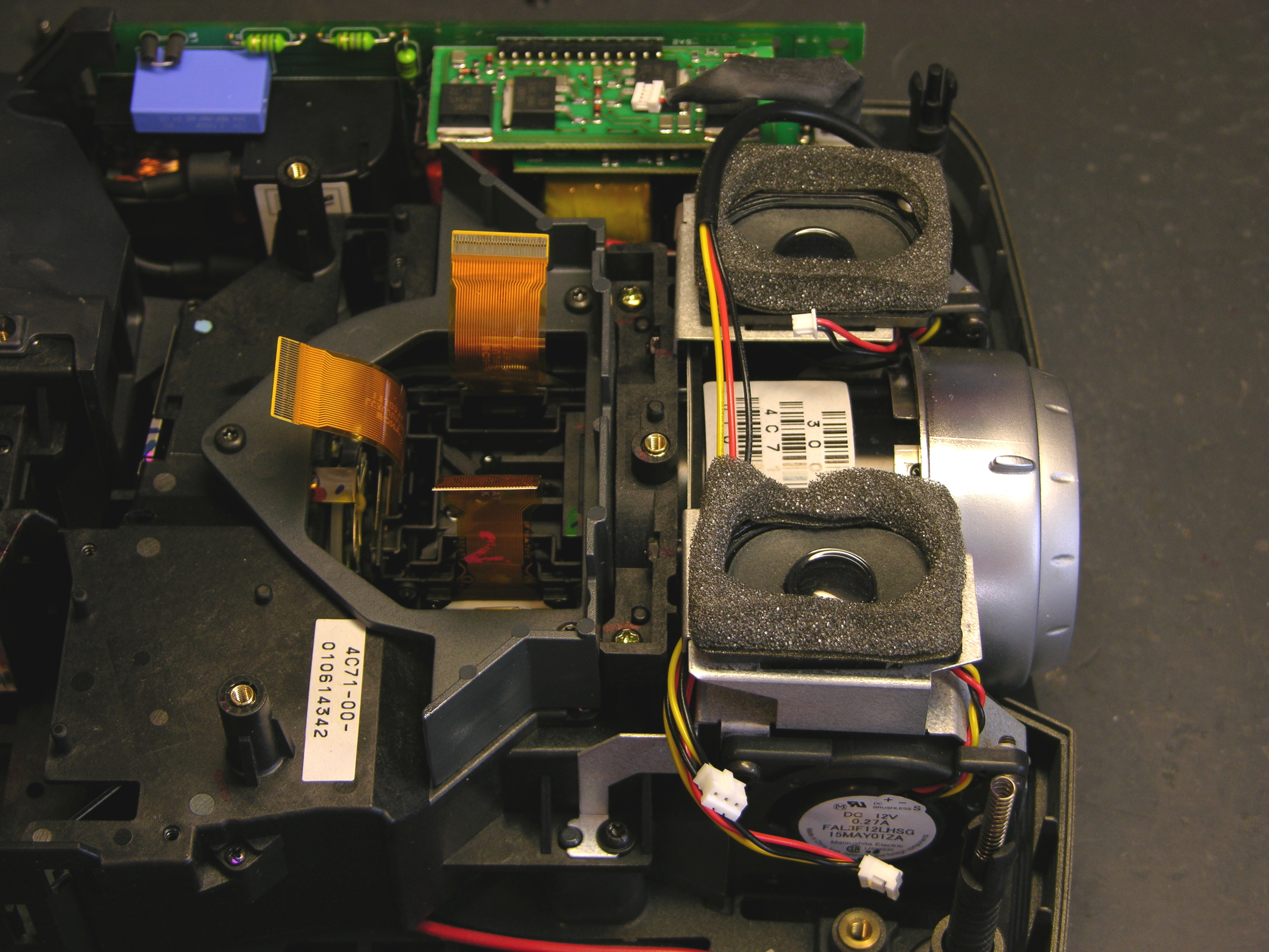
After popping the cover and removing the main circuit board, I could see most of the periscope-like light enclosure. I removed a couple of lenses that dropped in from above, which were clean, and looked at a couple of mirrors, which were also clean. The next thing I wanted to check was the LCDs.

Interior of InFocus LP290 Projector

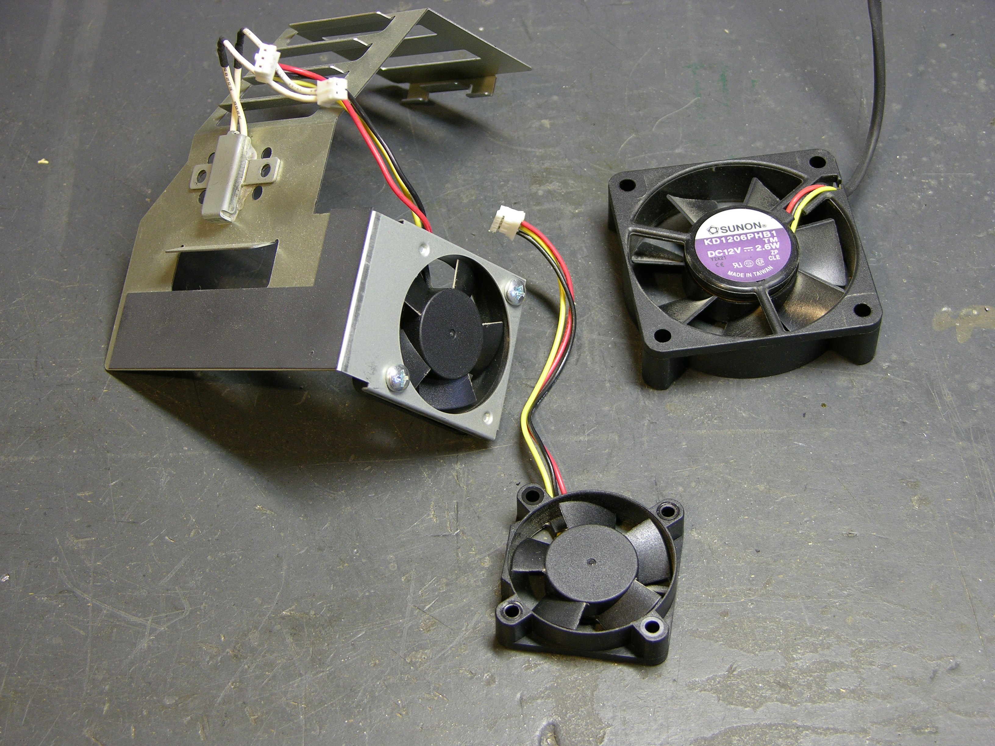
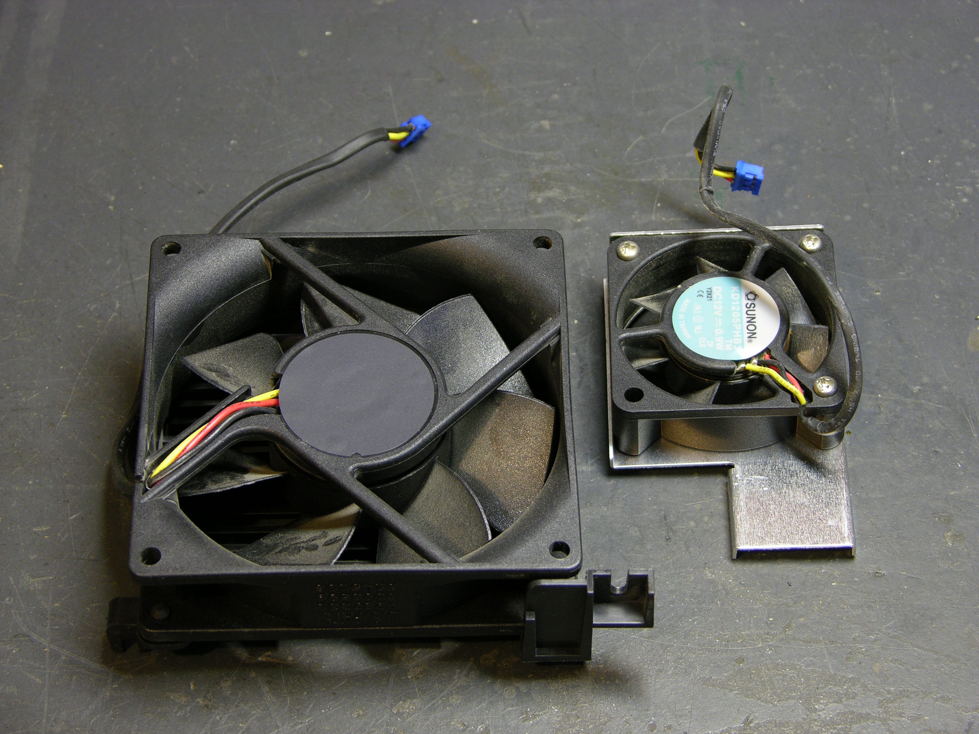
In order to get to them, I had to take off the collar above/around them, remove the two cooling fan / speaker assemblies, and remove the main lens. The LCDs were mounted to the lens carrier and looked fine; their removal left access to this cavity where the RGB light paths converge.

LCD cavity on InFocus LP290 projector

I didn’t notice it until later, but someone had already been here before. Loctite on the RG screw tabs and missing from the B tab.

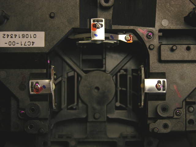
From a different angle, the problem was obvious.

Melted polarizing filter from InFocus LP290 projector

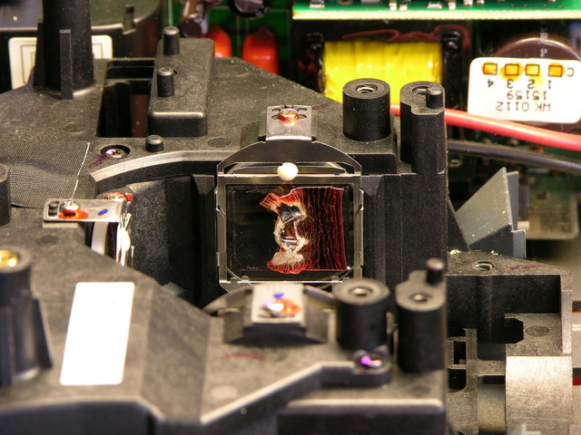
The filter between the blue light path and the blue LCD is all melty. Bad.

First things first. I gently peeled off the Bad, scrubbed all the goo off the glass carrier with Goo Gone, washed all the Goo Gone off with Dawn, rinsed the Dawn off with water, and dried the water off with a paper towel. (Life is sooooo complicated.)

Cleaned polarizing filter carrier from InFocus LP290 projector

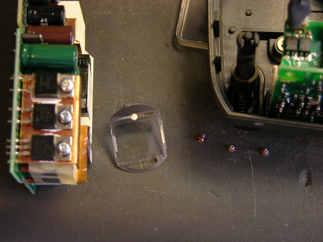
Here it is all shiny and ready for . . . whatever comes next.

While I was in there, I detached and examined the other two filters. They didn’t look colored, just a light neutral grey in a very familiar sort of way. Apparently the filter isn’t what makes the blue blue (that’s the blue half-mirror further upstream), so maybe I can just put it back together and see what happens.

Reinstalling the Filter Carrier

Assembly is the reverse of disassembly.

The projector is back together and emitting blue light when it should be emitting black. The Bad was the polarizing filter that makes the LCD do its thing, so I’m going to have to find another one and put it back. It’s still emitting shades of blue; it just puts out quite a bit of blue when it should be going all the way to black.

I’d welcome donation of a spare polarizing filter from a differently-ruined LP290, and I’m shopping for a broken one. But partly for sheer “I can’t believe you did that and I can’t believe you got it to work” value, I’m sorely tempted to get a polarizing filter somewhere else and see whether it’ll do the job. Like a photographic filter. Or an LCD from dead equipment. Or sunglasses. :-)

Of course, none of those are good ideas. It obviously gets hot inside the projector, and meltage problems are going to avalanche as the filter warps and discolors and becomes less transparent and absorbs more energy from the light and heats up and warps and discolors. So I’ll at least look around for a spare projector to cannibalize.

Power Supplies

The projector has the lamp cover interlock switch and AC-DC power supply on the starboard side and the DC-DC power supply and lamp ballast on the port side. The AC-DC supply is always on, and the DC-DC supply appears to be under control of the microprocessor that runs the soft power button and monitors the sensors scattered throughout the projector.

The AC-DC power supply checks out okay, as far as I can tell. All of the electrolytics test good with my Capacitor Wizard, and the three voltages (16.5V, 6.6V, and 3.3V) are present on the edge connector that plugs into the main board.

I took the projector parts over to Ron Tozier, and he suggested testing all the voltages with the projector in standby, with the projector on, and after the projector shuts itself off. That should help determine whether the failure is in the AC-DC power supply board (probably not), in the DC-DC board, or quite possibly with one of the sensors. He also noticed that the main board has nicely labelled test points for lots of voltages, including not only the raw AC-DC supply outputs but also regulated and switched voltages under microprocessor control.

I printed out a digital pic of the main board, highlighted all the power supply test points and wrote the standby and on voltages next to them, and am now waiting for the projector to shut itself off. Of course it would pick now to stay on for hours.

I do note that every time I turn it on, as it powers up the lamp, I hear a chittering sound like an ultra-high-pitched buzzing. I think it’s the ballast going out, and I’m pretty sure the projector would sense a ballast failure and shut itself down. So I suspect I have a pretty good idea what I’m going to find is causing that problem as well.