Archive for the ‘Salvage’ Category

X-Ray Control Panel???

Sunday, November 16th, 2008

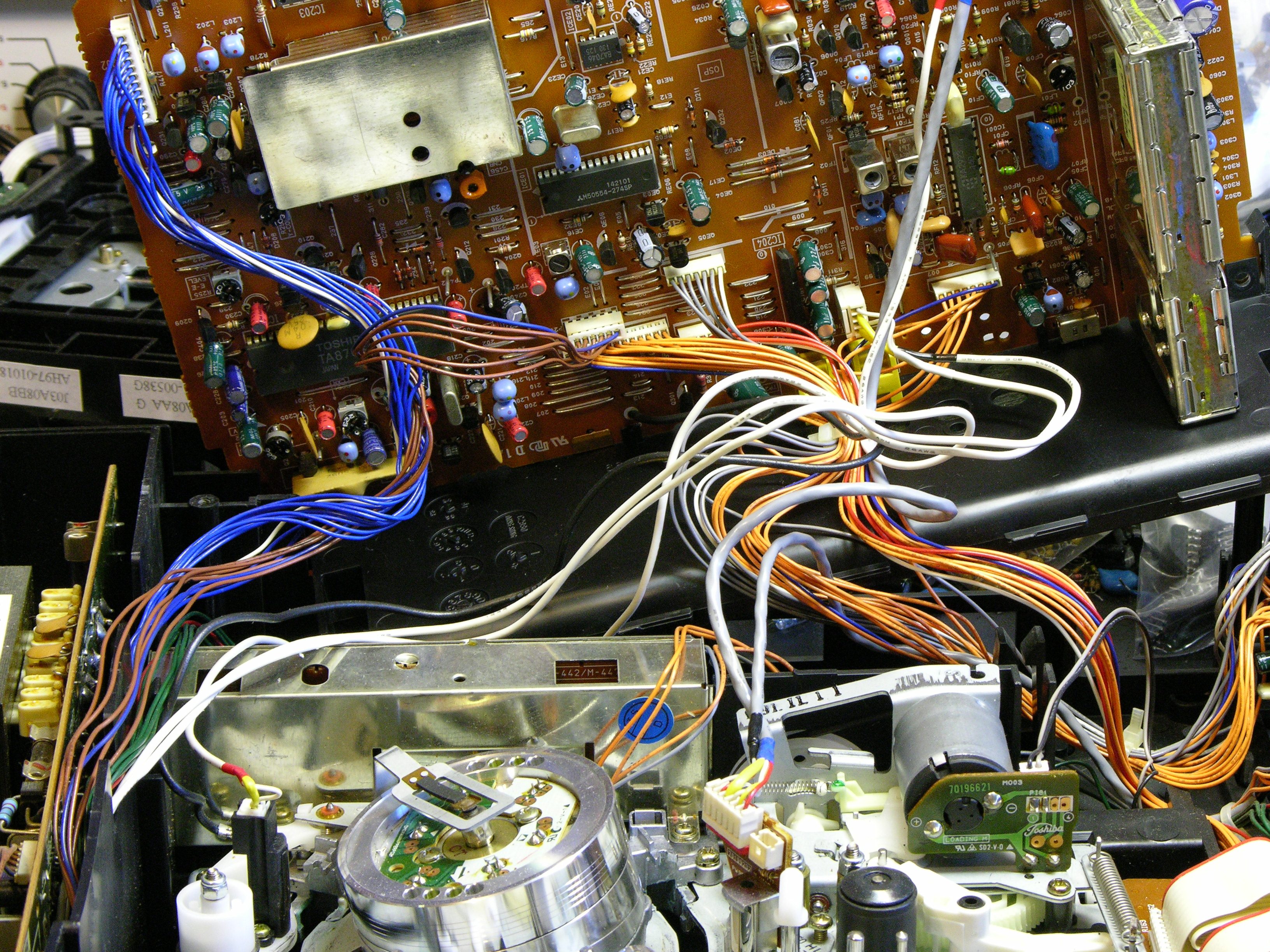
One of the electricians at work gave me a bunch of circuit boards from decommissioned equipment this week. It’s usually elevator stuff, so I hadn’t paid much attention to it other than to note the pretty colored wires.

XG controller panel, rear

The I was taking it out of my trunk to put into a “process later” pile when I noticed the front.

XG controller panel, front

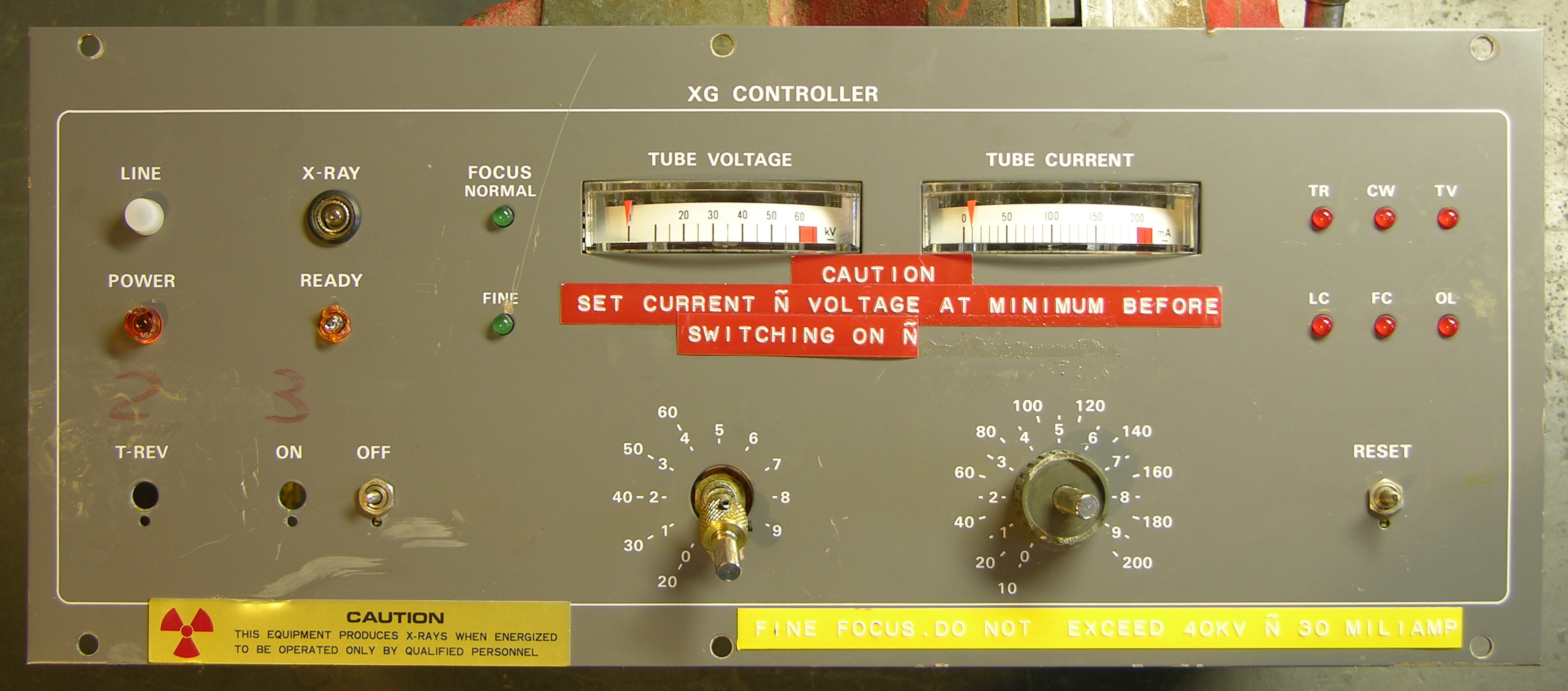
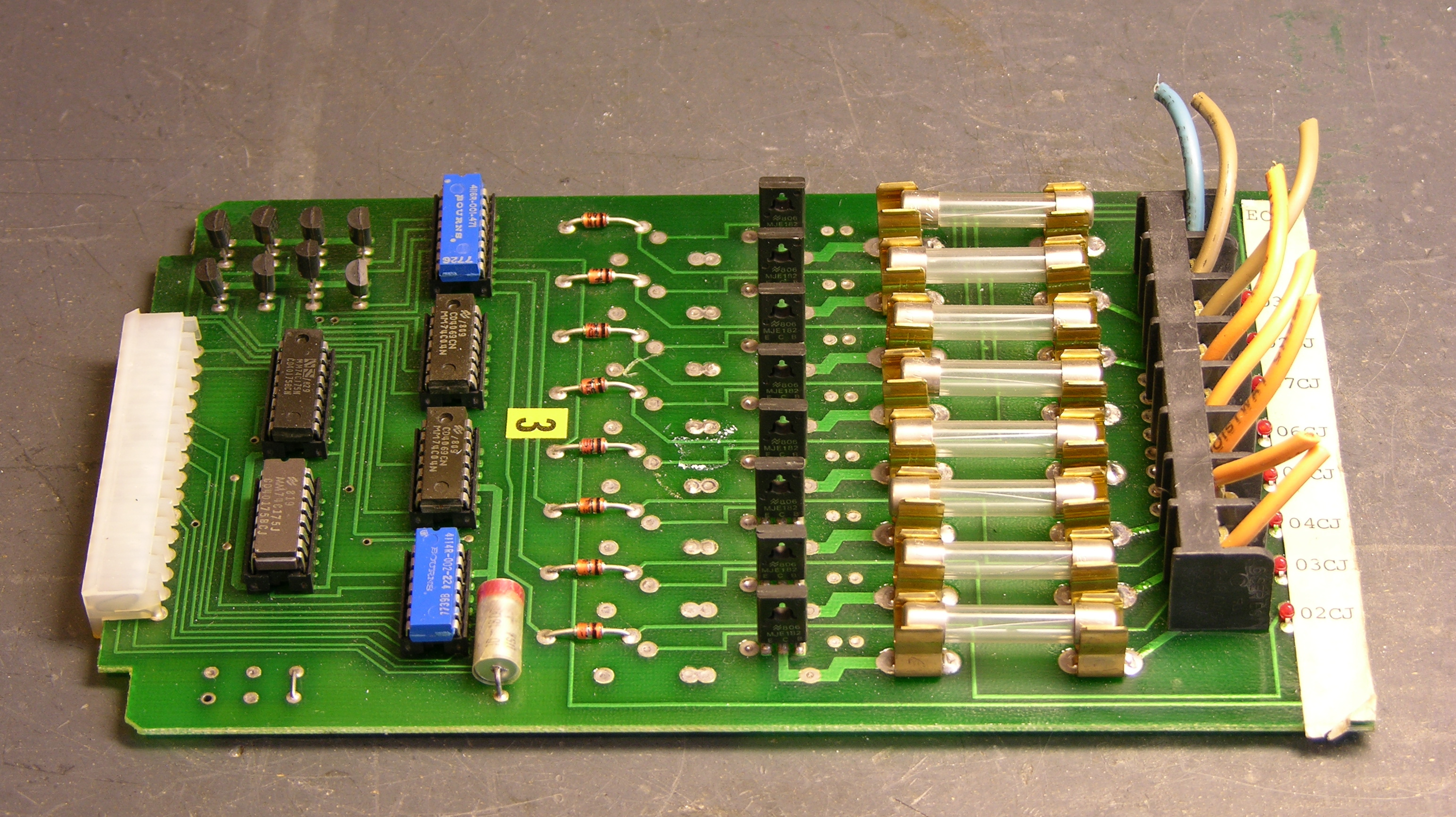
“X-Ray.” 60kV tube voltage. “Fine focus.” Whaaaa???

Combined with the way all the front-panel switches and knobs are bent and broken off, I’m guessing this was in one of the laboratories, some unfortunate researcher accidentally stepped in front of the beam and mutated into a creature with superhuman strength, and in the resulting chaos demolished the equipment. Since it was destroyed, now I have it. Cool!

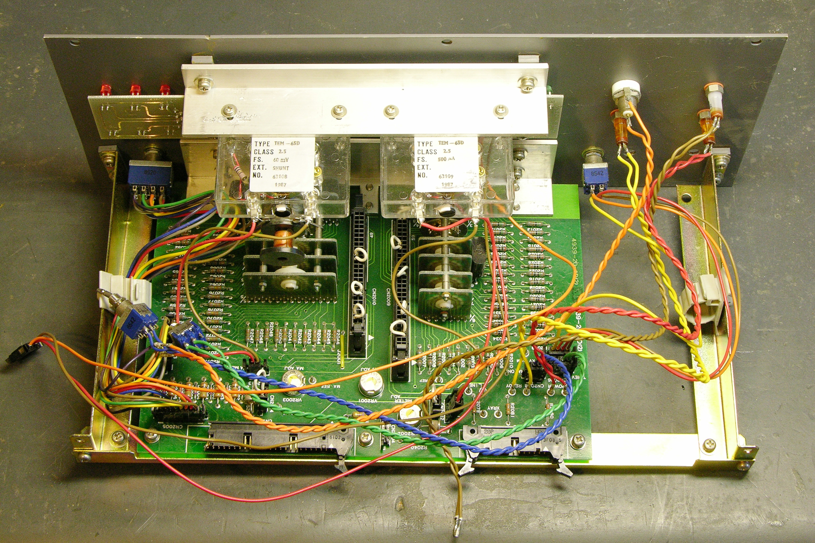
I went ahead and disassembled it tonight. Here’s a different view of the meters:

Edge-style panel meters

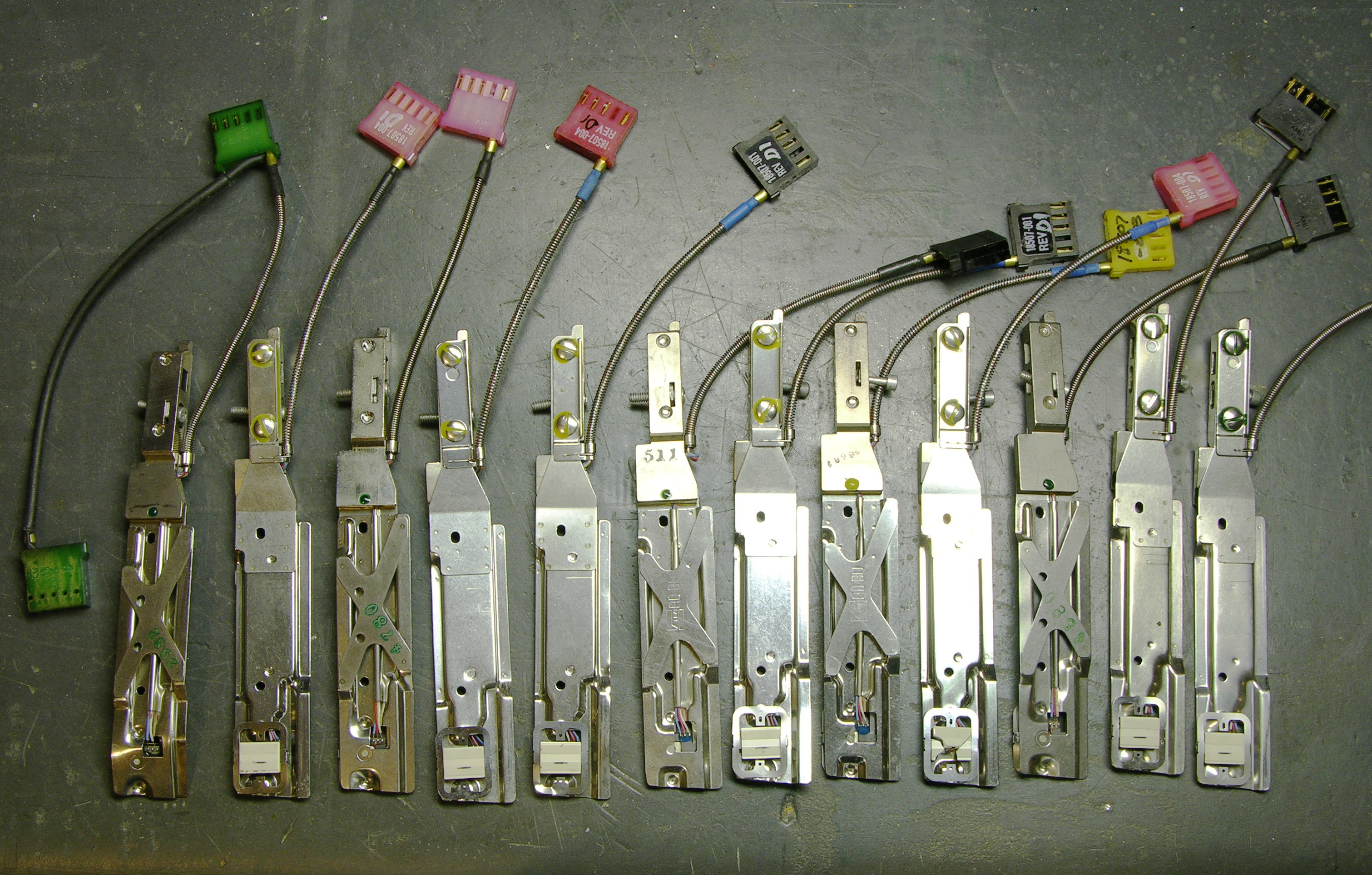
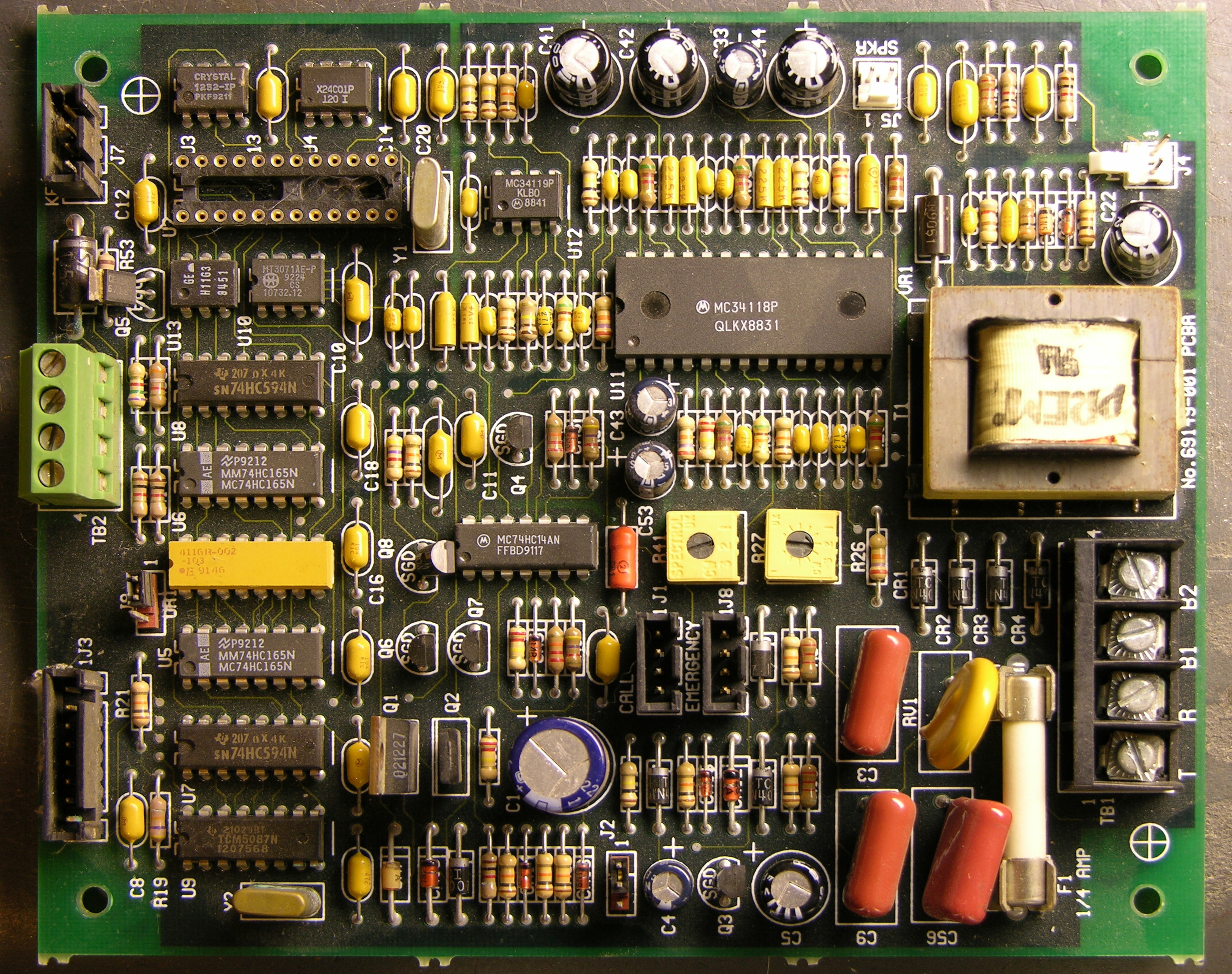
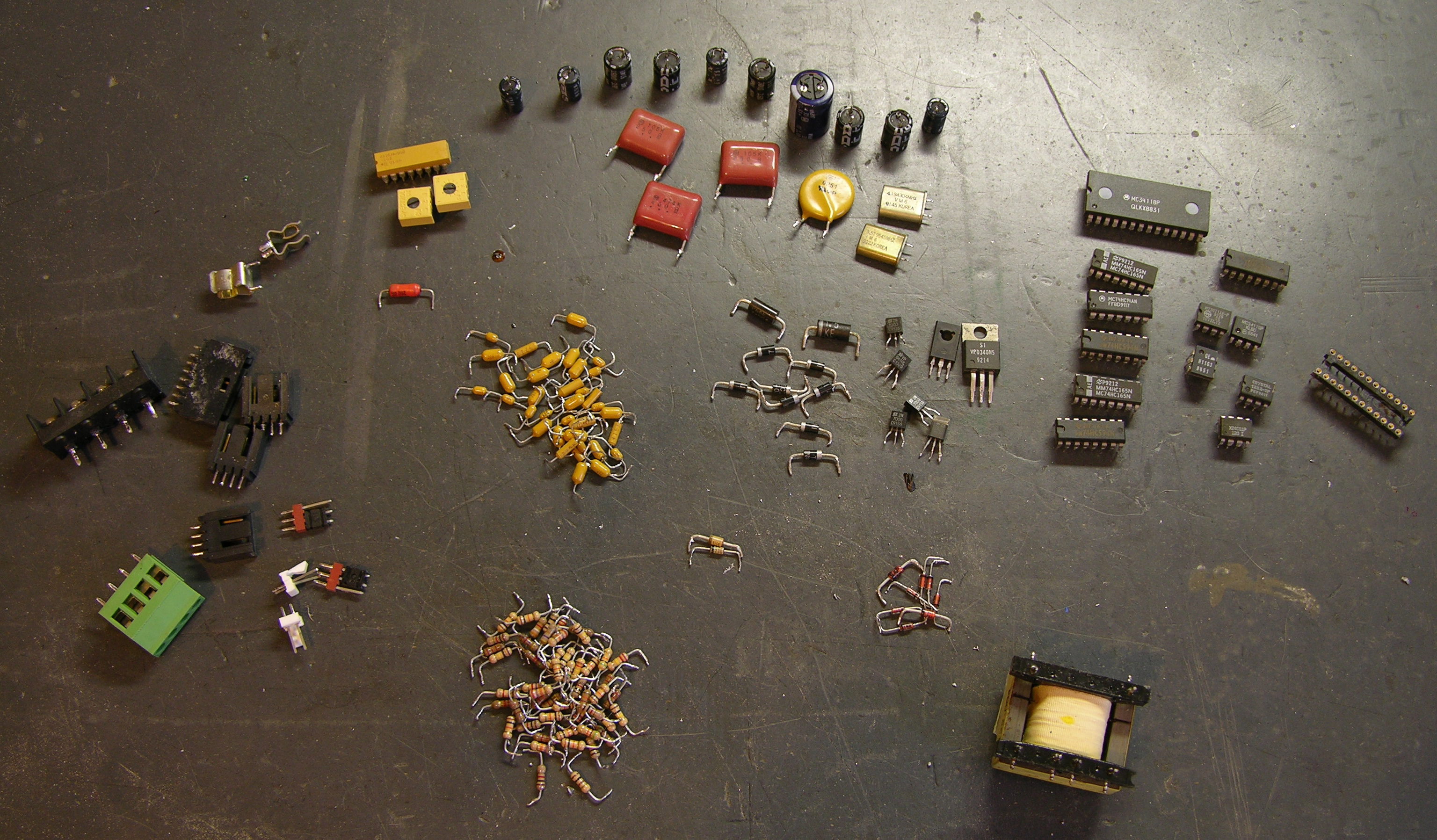
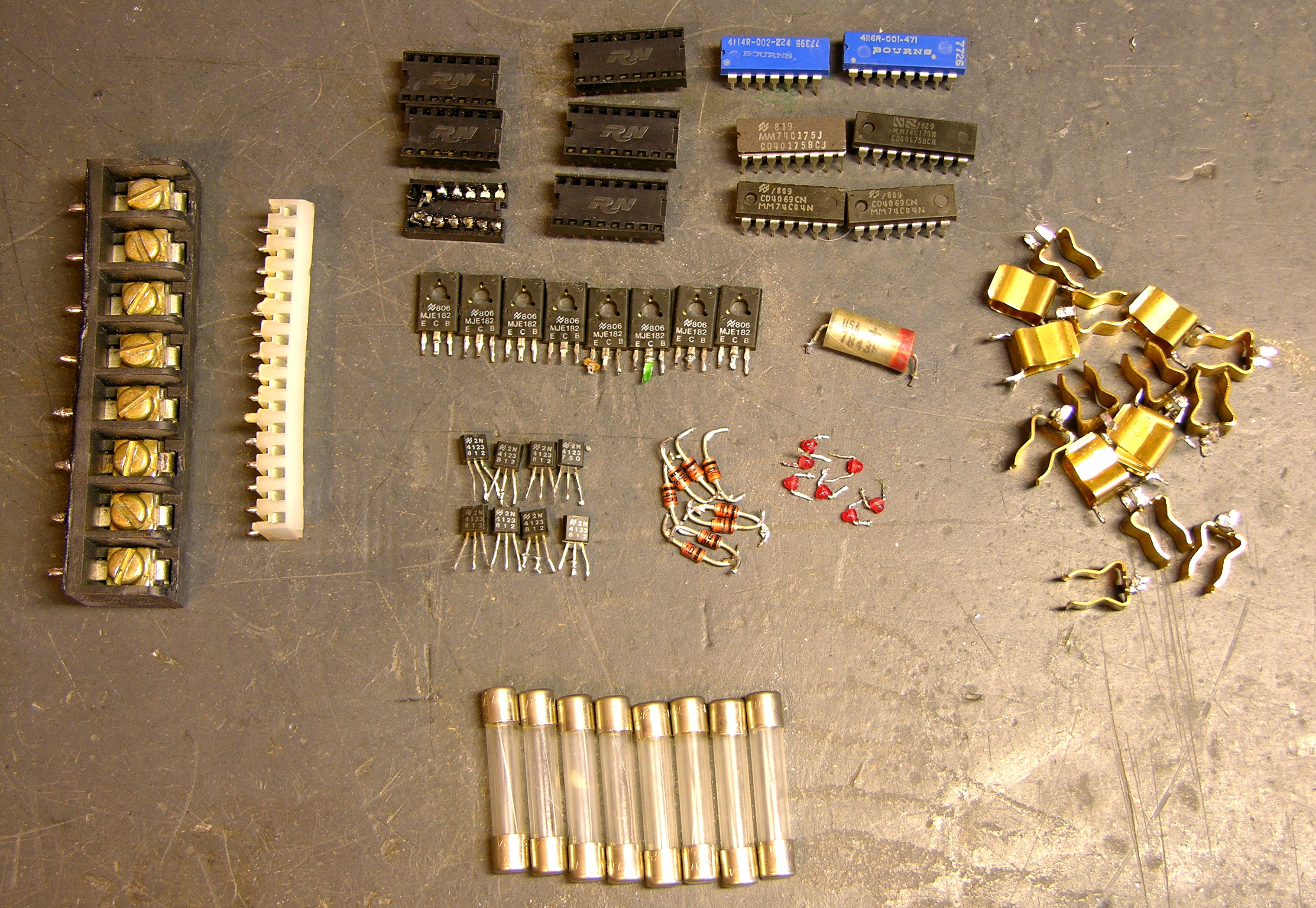
And there’s a big pile of connectors, resistors, and lovely wires on my workbench.

Cool Rotary Switches

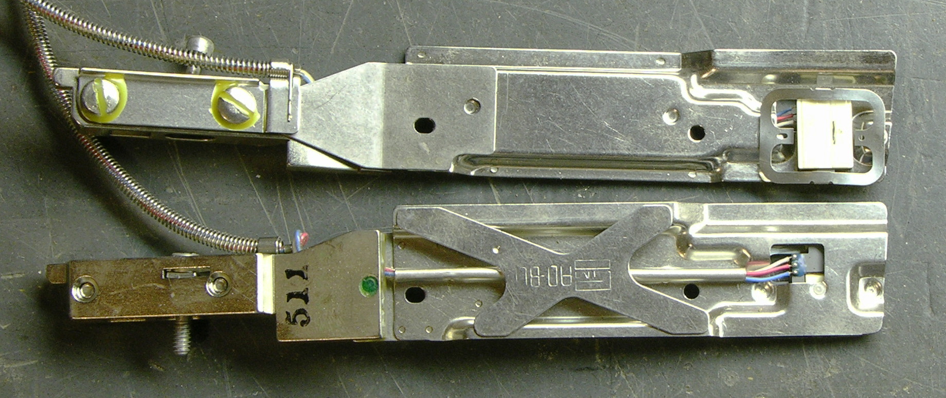
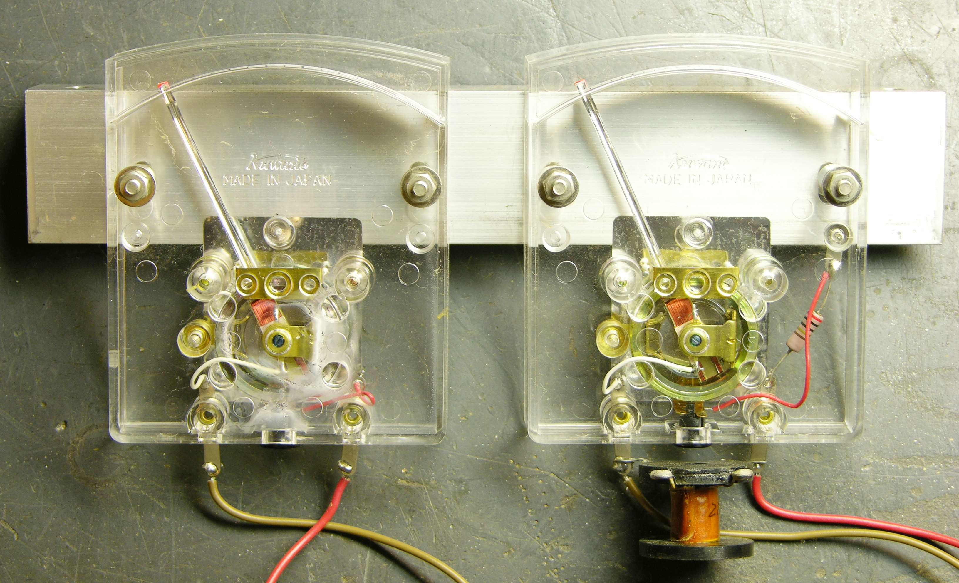
Here are the two rotary switch assemblies. Their knobs were broken off and their shafts bent, so they’re not working terribly well, but I’ve improved them a little.

Rotary multi-position switches

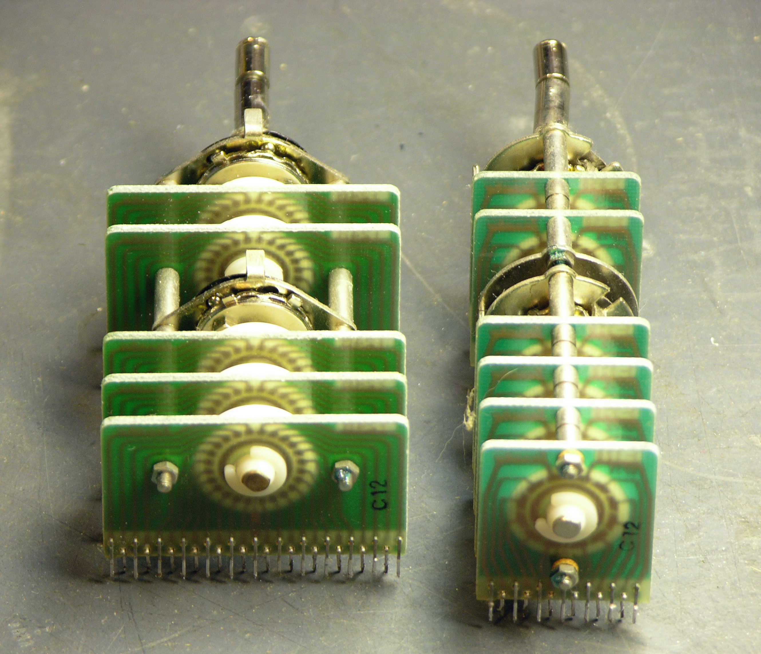
They have circuit boards that are ganged together, with the inner shaft turning the back set of switches (of course) and the outer shaft turning the front set.

Rotary multi-position switches

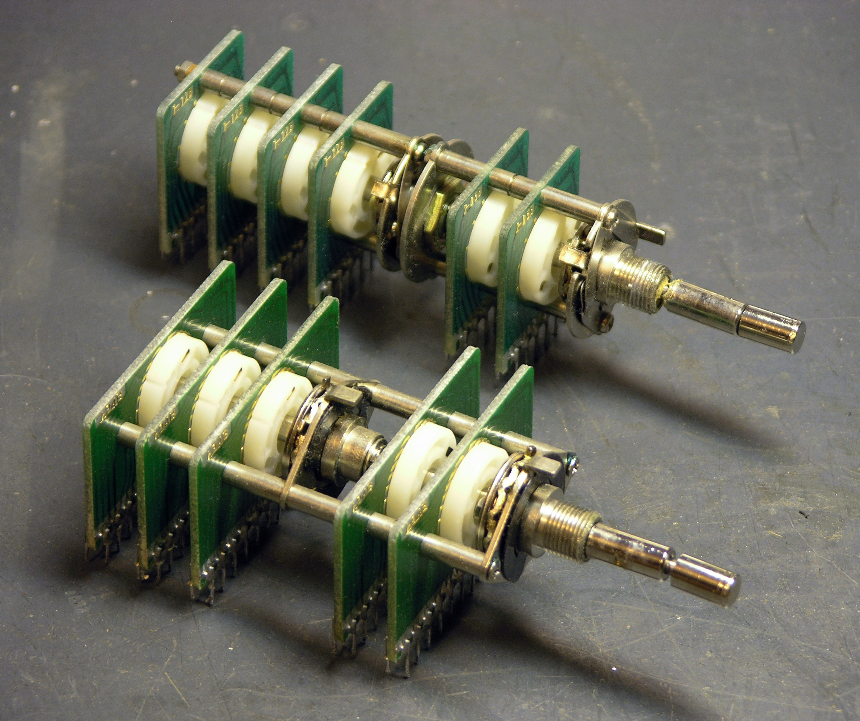
The mechanics of the assemblies are fairly intricate. You can click the picture (as always) for the full-resolution version if you want to follow along.

Rotary multi-position switches, partially disassembled

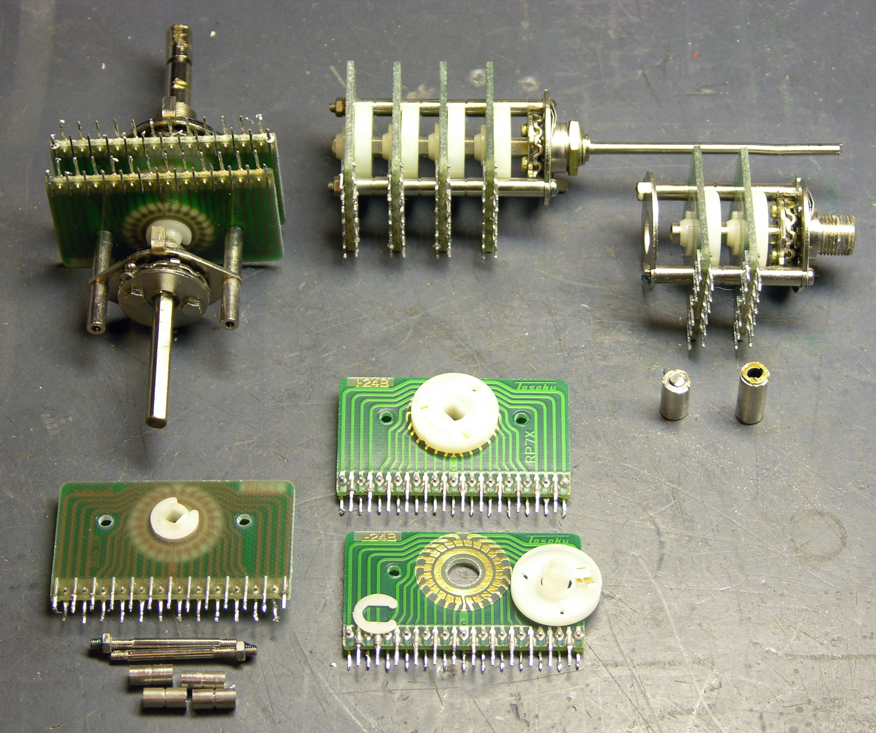
Clockwise from the bottom:

Every switch position is a separate trace on the PCBs, with 24 positions on the wide assembly, 12 positions on the rear part of the narrow assembly, and two sets of 5 positions on the front part of the narrow assembly. A wiper on the plastic rotor connects the PCB’s inner ring trace to each outer pad in turn.

In the upper left, you can see how the limits of rotation are set by two discs with tabs sticking out, which bolt onto the head end of the (sub-)shaft. The discs’ tabs stop against a rear-pointing tab on the head-end mounting plate, which is on the underside in this picture.

Shown at the top, the rear portion of the narrow assembly is still in good condition. It was pretty gummed up, but a few sprays of silicone lubricant got it turning nicely. The PCBs are mounted on a set of multiple threaded rods, threaded spacers, and unthreaded spacers. The rotor’s detent action is provided by the wavy disc on the back side of the mounting plate, a ball bearing sitting in a hole in the plate, and a leaf spring on the front side of the plate.

In the upper right, the front portion of the narrow assembly is okay, but the outer shaft that used to rotate it was sheared off at the base (shown immediately below it).

I had to saw the front knob off the narrow assembly’s shaft to get the assembly apart and make part of it usable. You can see that the kob appears to have been threaded onto the end of the shaft; but with a vise and a pliers, I was unable to turn it loose. The shaft had been pretty badly bent anyway, so I have no hard feelings about having to saw it off.

Idea for Rotary Switches

So I’ve actually been looking for rotary switches like this, and thinking of trying to make some myself. This unfortunately is not the form factor I need, but it shows the idea is sound.

The high school robotics team has strict rules they have to play by, and one of them is that the joysticks used to control the robots in non-autonomous mode must work like PC joysticks (I think the PIC that runs their control panel is charging and timing an RC circuit to determine the joystick position) and cannot have any supplemental power.

This wouldn’t matter, except that the linearity of the joysticks they have is poor; and with (apparently) only 8-bit sampling, there’s not as much they can do programmatically to correct the linearity as they’d like. So it takes a bit of programming effort to eliminate drift when the stick is physically centered; and then when they start to move the stick, the robot lurches into action with not much fine control over low speeds, and at high speeds is pretty much just maxed out.

Of course I assume if it were my robot, I could correct most of that in programming. :-) Still, that’s a lot to ask of high-school kids who are already making amazing engineering accomplishments on a very tight timeline.

So Ron (of the fundraising concert, and father of the team captain) would like to figure out how to build a new joystick that abides by the letter and spirit of the rules but gives finer control over low speeds and has really significant jumps up to maximum speed only when you floor it. Obviously he wants pots with an S curve response (log taper in both directions from center), and he hasn’t been able to find that commercially, at least not that he could retrofit into a joystick.

His idea was to do it discretely — come up with some sort of switching action, then connect that to a resistor ladder. He could play with the resistor ladder to his heart’s content until he got something that “felt” right for the application — make it pluggable and let the kids swap resistors until they got a response curve they liked. And he wasn’t too worried about the robot lurching as the joystick went from step to step on the ladder — he feels that relatively few values would suffice.

If these 24-position rotary switches could fit into a joystick’s gimbal assembly, they’d be fantastic for that! Reserve the middle 3-4 positions for a broad center band to eliminate home-position drift, then have ten more positions in each direction for different speeds.

Except I’m pretty sure the gimbal assembly has little 3/4″-diameter pots right there on it, and these big PCB things just wouldn’t work. Feh.

I thought about etching my own PCBs to replace the wafers inside a couple of sacrificial pots, but I hadn’t figured out quite how to route all the wires out.

Open to suggestions here.

Salvaging a Pile of VCRs

Monday, November 10th, 2008

VCR mechanics, PCB, and wiring harnesses

A few weeks ago, I tore into a stack of dead VCRs, salvaging interesting parts, recycling a lot of metal and plastic, and intending to reduce the volume they consumed. Unfortunately, the resulting lesser volume has been mounded up on my workbench instead of neatly stacked in the garage.

The insides of VCRs are familiar to most tinkerers, but some of the bits are more interesting in bulk.

(more…)

Rackmount Stuff from Slim’s “Dump”

Monday, October 13th, 2008

Here’s the first batch of stuff from Slim’s “Dump” — rackmount equipment that I can’t identify as being associated with anything else from out there.

Rackmount stuff from Slim's dump

I can’t tell that any of this stuff as still useful (which presumably has something to do with why it was out in the Dump in the first place), so it’s destined for disassembly, component removal, case reuse, and recycling. If there’s anything that strikes you as useful, throw a comment down below about what it’s good for, offer to pay me what it’s worth to you plus shipping costs, and I bet we can work something out. I’d love to see some of it go to someone who’d actually make use of it.

(more…)

(Ancient) Disk Drive Heads

Monday, October 6th, 2008

Lawrence’s son Jacob has been cleaning out their basement, and recently dismantled a TI disk drive about half the size of a washing machine — the kind where you load big cylindrical disk packs down into the center. They gave me a bunch of circuits from it to recycle, and I was intrigued by the disk heads.

TI disk drive heads

I grabbed them at first for the .1″ header connectors, and I was tickled by the spring armor around the wires, and then I decided I just liked the whole things.

TI disk drive heads, closeup

Enough to take a few pictures, anyway. But now I think it’s time to keep the wiring harnesses and ditch the rest.

Heh — if I got TGIMBOEJ, I’d throw some of these in. :-)

Wire-Scrounging Challenge

Tuesday, August 5th, 2008

I brought my “Arduino on the go” along to New Mexico, but discovered I’d installed a pushbutton on the breadboard in a spot that was already wired to ground, making the button always “pressed.” In order to move it, I needed more jumper wires; and due to a combination of hurry and hubris, I had brought none along.

I needed some 24- to 26-gauge solid wire, in a cabin, on a mountain (excavaaaaaating for a mine). The nearest Radio Shack was twenty miles and about forty minutes away, and I couldn’t think of any store in Angel Fire likely to have wire for me.

So, where would you scrounge up wire in an emergency? I’m actually interested in suggestions — add them to the comments if you can come up with something other than my ideas. I didn’t have anything along that I could take apart for wire, I didn’t have a soldering iron to tin stranded wire, and I wasn’t willing to damage anything in the cabin, the car, or the area.

(more…)

Swell Pedal from Baldwin Model 5 Organ

Thursday, July 3rd, 2008

July 7, 2008

Welcome, MAKE: Blog readers!

Whoever posted this to the MAKE: Blog jumped the gun a bit — I haven’t interfaced anything to a synthesizer yet. What I found in the Baldwin pedal isn’t suitable for interfacing and is (in my opinion) worthy of preservation, so this post is just a teardown of the Baldwin pedal showing the intriguing mechanism inside.

I have since gathered all the parts I’m going to use to build the MIDI volume/expression pedal and expect to do that within a few days; so if you’re interested, please check back!


I want to build a volume pedal for my synthesizer(s), and I figured it’d be easier to do if I started with . .  a volume pedal. So last night I went to storage and pulled the swell pedal out of Jacob’s most recently discarded electric organ, a Baldwin Model 5.

Baldwin Model 5 organ swell pedal, front view

It’s actually quite a bit higher off the floor and more steeply angled than would really suit me; but I had it on hand and figured I might as well start working with it. As it turns out, I’m not going to retrofit this, and I’ll show you why in a little bit.

Baldwin Model 5 organ swell pedal, mechanism

Rocking the pedal forward pushes the square lever away from the box, and rocking it back pushes the lever toward the box and presses a pin at the base of the lever into the box.

Baldwin Model 5 organ swell pedal, electronics enclosure

The lever and box assembly looks kind of like a giant microswitch. Or a bird with a long neck.

Baldwin Model 5 organ swell pedal, electronics mechanism

Here’s the part that makes me say, “Wow.” Apparently potentiometers hadn’t been invented yet (I think I’m joking), or weren’t available with a high enough power rating to use in this volume control circuit.

The volume pedal’s lever presses against a ladder of leaf switches (it’s hard to see, but all the contacts at the left end of the leaves are normally open, but only barely) wired to a resistor ladder. Pressing the pedal connects together increasing numbers of leaves and shorts across increasing numbers of resistors. Wow, wow, wow.

I just don’t feel right about dismantling this to stick in a potentiometer (nor are the mechanics of it really built to make that easy).

So now I’m looking for another swell pedal (with a pot) to repurpose, ideally a twin swell pedal like what’s on Jacob’s current organ. I don’t find much on eBay, and I’m not sure where else to look.

Free: Boxed Manuals → Cases for Prototyping On the Go?

Wednesday, June 25th, 2008

I’ve been saving these relics of the Information Age forever, initially because I had the computers to go with them, then out of nostalgia, then because I forgot I had them, and now because it seems like the boxes should be useful. But really, I’d just like them to go away.

Anybody want some three-ring binders with matching boxes, maybe to put an Arduino and breadboard in to take with you on vacation and play with circuits when you’re stuck in Saint-Tropez for a couple of weeks with nothing to do? The rings oughtta be good for holding baggies of parts, or something.

Seriously, if anyone wants any of these, they’re yours for the cost of shipping. The MS-DOS Operating System is missing one of the two volumes from the double-wide case; the Wordstar and Operating Instructions are intact in single-wides.

Desoldering with a Heat Gun DOESN’T Ruin Electrolytics

Sunday, May 18th, 2008

After repairing the Alesis monitor speakers by replacing overheated electrolytic capacitors, and then having one break again within a couple of minutes the first time I used it, I started to get a little paranoid about electrolytics and heat. In particular, I wondered, am I baking the electrolyte and ruining the capacitors when I bulk-desolder with my heat gun?

Gave it a little test today. The power supply board from the dead Optoma projector had a bunch of nice electrolytics on it, so I tested their ESR with my Capacitor Wizard, desoldered the board with the heat gun, and tested the caps again.

No perceptible increase in ESR, and I’m really glad to know that I haven’t been (directly) ruining capacitors all along. Yes, the extra heat probably speeds them on their way; but at least it’s not immediately fatal.

How to Sort and Store Salvaged Electronic Parts

Sunday, January 27th, 2008

Friday night, I harvested the components from this board using the heat gun.

Circuit board

Time spent

  • straightening leads with a chisel: 10 minutes
  • heating and pulling components: 15 minutes
  • sorting and putting away components: half an hour

And the sorting time would have been spent anyway if I’d bought the parts in a grab bag.

Salvaged electronic parts

The take:

  • several nice terminal strips, connectors, and a fuse holder
  • a handful each of electrolytic and non-electrolytic capacitors
  • a handful of resistors
  • a handful of diodes, including two Zeners and some 1N4007 rectifiers
  • miscellaneous transistors
  • miscellaneous ICs, including a speakerphone IC (ah! so this was a dead board from a campus emergency call system), tone generator and detector, low-power audio amplifier, and serial EEPROM
  • the inevitable transformer

Not bad, to my way of thinking, for an hour’s free entertainment.

Sorting and Storing

After salvage comes sorting and storing, which are mostly common sense. Here are some things I’ve found to minimize the tedium of sorting and to optimize storage.

My basic principle of sorting is to do so hierarchically. So I first group simmilar components, as shown above. Some components, like connectors and digital logic chips, go straight into bins without further sorting by type or value.

Connector and 7400 logic drawers

Resistors and capacitors I sort by decade (multiple of 10) immediately and by specific value later.

Sorted capacitors

If I find a batch of several identical capacitors, I like to keep them together in a small bag. If I’m working on a project and want identical caps for aesthetic or technical reasons, it’s easier to grab a bag than to pick through loose caps in a drawer.

Capacitor drawers

Then the capacitors (and bags) go into drawers labeled (approximately) by decade — electrolytics above, others below. Common values of physically larger caps may get split up into their own drawers.

Sorted resistors

It’s easy to pick out 10X-valued resistors while sorting by decade, so I do that up front (the upper row — 10Ω, 100Ω, 1KΩ, 10KΩ, and 100KΩ). The mixed resistors (lower row) go into a decade drawer

Resistor decade drawer

and get put into a row in the parts cabinet for now.

Resistor drawers

Then sometime later, I’ll go through the decade drawers and sort by individual value.

resistor tray

I’ve seen university EE stockrooms with enough parts bins to have every resistor value in a separate drawer, but most of us don’t have that much money or room for storage. I suggest going to hobby/craft stores and looking for storage solutions designed for beads or for embroidery floss. Bead storage in particular is good about sealing each compartment when the lid is closed, to keep beads resistors from migrating about when the storage is moved or shaken.

I spent several evenings driving all around Wichita a few years ago and came up with these trays, I think for floss, which are perfect for salvaged resistors. (New resistors may need the leads bent a bit to fit in the drawers.) I bought a tray for each decade and have a stack of them sitting beside my workbench.

Most of the resistors I salvage are 5%, which has 24 standard values per decade. I made a spreadsheet of all such values to fit on adhesive return address labels, Avery number 5267, and stuck a label into each spot in the tray. I’d offer the spreadsheet for download, but for some reason I can’t find it any more. :-(

How to Salvage Electronic Parts

Saturday, January 19th, 2008

Knowing what kind of equipment to salvage for electronic components isn’t enough; you have to know how to get the parts out, or you’re just stockpiling junk. Through-hole ICs may be best stored on the original circuit boards to salvage when needed; but common components like resistors, capacitors, and diodes are much more economical to salvage in bulk, then sort, store, and have ready on demand.

I desolder with a heat gun and pull the components out with pliers. I destroy a few components on nearly every board I salvage; but it’s incredibly fast compared to any other method I’ve tried. For me, the time savings I discovered when I switched to using a heat gun was what made it really worthwhile to salvage components in bulk and stock up my parts bins.

Circuit board to salvage

Here’s a circuit board that one of the electricians at work brought me. I don’t know what it does; but he works a lot with the elevators and it’s probably something out of an elevator control system.

It’s not representative of the resistor- and capacitor-laden boards I particularly advocate salvaging; but I had it on hand and it does serve to demonstrate my method.

Uncrimping Component Leads

Through-hole components on commercially-produced boards tend to have their pins crimped on the solder side, to hold the components in place during the time between stuffing and soldering. Even with the solder melted, you can’t pull out a crimped component with pliers, so the first step is uncrimping the leads.

Uncrimping component leads with chisel

I use an cheap 1/4″-tip wood chisel from a dump bin at my local Ace Hardware store. (This is “my best $3 chisel” that I’ve referred to before — my real wood chisels never come anywhere near metal.) It doesn’t need to be sharp, but the edge should be fairly straight. I use a similarly cheap diamond honing board to clean up the nicked edge from time to time.

I push the chisel into the solder under the lead and lever up to straighten it. It’s important to get the chisel edge all the way to where the lead comes out of the hole, or you won’t be straightening the lead; you’ll be putting another zig in its zag.

Keep your other hand out of the path of the chisel. I’ve slipped the chisel off of leads, cut leads clean off, and tried to pry up solder pools that didn’t have leads in them. All of these result in a narrow, sharp object moving forward at high speed with a fair bit of pressure behind it. Again, think about where the chisel is going to go when it slips and keep your fingers out of the way.

It took only a couple of minutes to uncrimp the few leads on this board. Larger boards may take five to ten minutes; CRT motherboards can take half an hour, and I tend to do them in sections because uncrimping leads is really tedious and boring.

Heating and Removing Components

Once the leads are uncrimped, I clamp an edge of the board into my bench vise and get ready to heat it up. You need a bench vise that’s heavy or bolted down — you’re going to be prying and wiggling on the components quite a bit to get them out.

Still life with bench vise and heat gun

Now is a good time to remove fuses from holders, and optionally remove any socketed components from their sockets as well.

I use a cheap heat gun that I got for $15 at Harbor Freight. I regard it as a disposable item — I go through one in about a year (during which time I’ve salvaged far more than $15 of components) and go buy another.

Starting at the bottom edge of the board, I heat the solder side with the gun 1-2″ away until the solder melts, then pull out the components with a needlenose pliers and drop them in a cup. It’s faster and easier for me to put them in a container and sort them later than to place them carefully on my workbench and have them get brushed around, but your mileage may vary.

Some notes about the actual desoldering and component removal process:

  • The first component is going to take a long time to heat up. Be patient; pulling before the solder is fully melted will just break the part.
  • You can see the solder melt. Watch for it.
  • Start at the bottom and work up a column, angling the heat gun in the direction you want to go. It’ll start melting the next component’s solder while you’re removing the previous one. You can go quite fast on a stack of properly uncrimped resistors.
  • Get out the regular pliers for larger items, and particularly for DIP components. Rock them back and forth very gently until you can see that all the pins are loose, then slip them free.
  • Don’t hang onto a resistor lead with the pliers while you’re heating it — you’re just making a heatsink and preventing the solder from melting. Heat the solder, then grab quickly with the pliers and pull. You may get both leads in one pull; or you may get one end loose, readjust your grip, and get the other end.
  • TO-220 parts may fit tightly enough that they don’t want to come loose even after the solder melts. This can mean pulling the plating out of the through-holes, which then means cleaning the tubes off the leads later. A giant 3/8″ chisel-tip soldering iron laid across all three leads will pop a TO-220 free in an instant.
  • PC boards are flexible, especially when hot. Long strip connectors may require freeing one end and bending both connector and board as you work along the connector to free the remaining pins.
  • Larger heatsinks (PC power supplies and CRT motherboards) may have tabs that need to be untwisted, and their tabs or posts may fit tightly through barely large enough holes in the circuit board. If necessary, save them for last and force them out with large pliers.

This sounds obvious, but when you’re done desoldering, the circuit board is still hot. I hold it with pliers while loosening the vise, then lay it on the concrete floor to suck the heat out.

Scorched circuit board

Make no mistake, this is a destructive process. The circuit board will be ruined, and the fumes from scorched fiberglass are probably not good for your health nor for your relationship with your significant other or housemates. It’s best to do this as close to the outdoors as you can get and with windows open and forced air ventilation, if you have the option.

Finally, recycle the board if you can. We have a very thorough curbside recycling program here, and I’ve set out a large box of stripped circuit boards (with an appropriate note) for copper reclamation.

Sorting the Spoils

Here’s the cup into which I dropped the parts as I was pulling them:

Cup of salvaged electronic components

And the parts sorted on my workbench:

Salvaged electronic components

I got a couple of terminal strips, several DIP sockets (one irreparably damaged), four TTL ICs and two resistor packs, eight NPN transistors, diodes, LEDs, one capacitor, and fuses and fuse holders. Not great, but not bad for fifteen minutes’ work.