Replacing My PowerBook Screen, Part 01: G4 500 Disassembly, Bottom Side
Quick Links
Background
Part 1: G4 500 Disassembly, Bottom Side
Part 2: G4 500 Disassembly, Top Side
Part 3: G4 500 Disassembly, Back Edge Screws
Part 4: G4 500 Disassembly, Removing the MB and Screen
Part 5: G4 550 Disassembly, Bottom Side
Part 6: G4 550 Disassembly, Top Side
Part 7: G4 550 Disassembly, Back Edge
Part 8: G4 550 Disassembly, Removing the MB and Screen
Part 9: G4 550 Reassembly, Screen
Part 10: G4 550 Reassembly, Motherboard
Part 11: G4 550 Reassembly, Top Side
Part 12: G4 550 Reassembly, Bottom Side
Aftereffects
Motherboard Screws, Bottom Side
I had already removed the battery and eight Phillips #1 screws holding on the back cover (locations identified in cyan), the back cover itself, and the hard drive (which doesn’t need to be removed to get the motherboard out, but is missing from the pictures). From here on out, I’ll write in the form of instructions, optimizing operations in the most efficient order rather than the back-and-forth order in which I did them (although occasionally editorializing about my own inefficiencies).
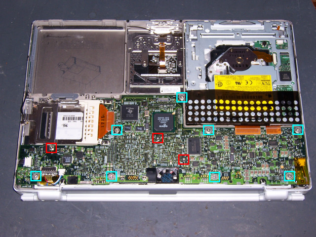
With the notebook closed, the bottom side up, and the battery compartment away from you, remove the three screws still holding down the motherboard at the locations shown in red, using a Torx #8 screwdriver. Almost everything throughout the two PowerBooks is held together with T8 screws, so if you don’t have the right driver for them, go get one now. Yeah, you can maneuver Torx screws with a very fine straight-bladed screwdriver, but it is so not worth it.
My set of small Torx screwdrivers is made by Wiha and purchased at Lloyd’s Electronics. I only have down to size 7 and I see Wiha has 6 and 5 available, so I guess I need to order a couple more.
Whenever I remove multiple screws from a case like this, I always set them out on a work surface in a pattern corresponding to their locations in the device, so I can be sure to get the right screw back into the right location. While disassembling these computers, I also made a diagram showing the screw locations at each stage, so that (for example) I didn’t put one of the motherboard screws back into a hole for a case screw during reassembly (and still did anyway).
Motherboard Connectors, Bottom Side
Unplug the snap-on connectors for the hard drive (upper middle) and DVD drive (two on the right upper edge). I used the flat blade of my geeky complimentary advertising clip-on screwdriver to pry them up gently from beneath–without crushing the surface-mount components on the board. Don’t bother unsnapping the PCMCIA connector–the socket will come with the motherboard. Also disconnect the slide-in video and backlight connectors in the lower left, the “heartbeat” light connector on the right, and the connector of all black wires on the left.
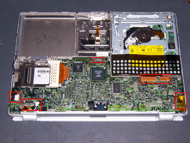
Don’t try to lift the board yet–it’s still connected from the top side.
Next: G4 500 Disassembly, Top Side
Sections
Background
Part 1: G4 500 Disassembly, Bottom Side
Part 2: G4 500 Disassembly, Top Side
Part 3: G4 500 Disassembly, Back Edge Screws
Part 4: G4 500 Disassembly, Removing the MB and Screen
Part 5: G4 550 Disassembly, Bottom Side
Part 6: G4 550 Disassembly, Top Side
Part 7: G4 550 Disassembly, Back Edge
Part 8: G4 550 Disassembly, Removing the MB and Screen
Part 9: G4 550 Reassembly, Screen
Part 10: G4 550 Reassembly, Motherboard
Part 11: G4 550 Reassembly, Top Side
Part 12: G4 550 Reassembly, Bottom Side
Aftereffects