Replacing My PowerBook Screen, Part 11: G4 550 Reassembly, Top Side
Quick Links
Background
Part 1: G4 500 Disassembly, Bottom Side
Part 2: G4 500 Disassembly, Top Side
Part 3: G4 500 Disassembly, Back Edge Screws
Part 4: G4 500 Disassembly, Removing the MB and Screen
Part 5: G4 550 Disassembly, Bottom Side
Part 6: G4 550 Disassembly, Top Side
Part 7: G4 550 Disassembly, Back Edge
Part 8: G4 550 Disassembly, Removing the MB and Screen
Part 9: G4 550 Reassembly, Screen
Part 10: G4 550 Reassembly, Motherboard
Part 11: G4 550 Reassembly, Top Side
Part 12: G4 550 Reassembly, Bottom Side
Aftereffects
Reattaching the Top Side
Opening the lid of the computer and standing it on edge, note that the modem daughterboard, found in the upper left area underneath the keyboard, is loose. It has a connector on its underside that needs to snap into the motherboard similar to the hard drive cables. Manipulating the modem card and the motherboard from both sides, fit the connectors together and snap them closed.
Set the computer down in normal operating position, and start with the two small T8 screws that hold the lower PCMCIA card to the motherboard (red arrow)–you may as well get the worst part over with. As during assembly, pull the wires up and back onto the shield to make room to access down to the screws. If your screwdriver is magnetic enough, you may have very little difficulty getting these screws started; I had to set them into place with bent-nose pliers and then reach in with the Torx driver to turn them. Tighten them completely.
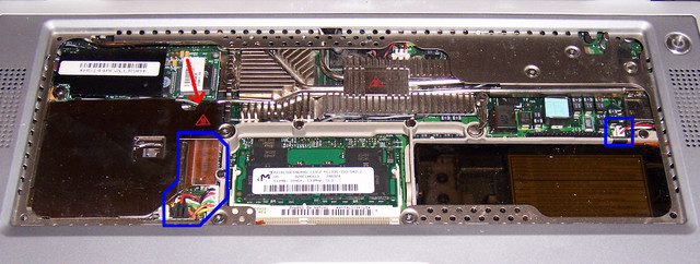
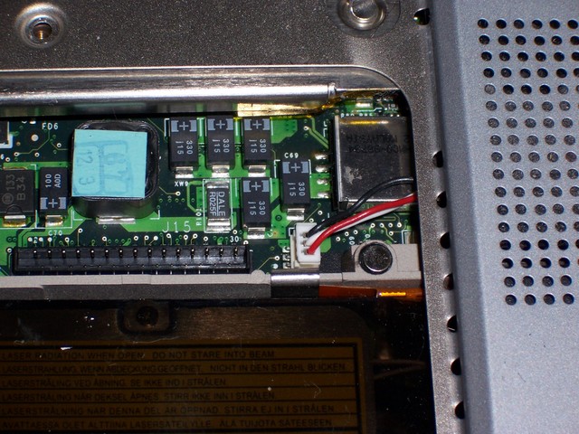
Follow by snapping in the PCMCIA connector and plugging in the battery cable (blue box); then reconnect the red, white, and black cable on the right.
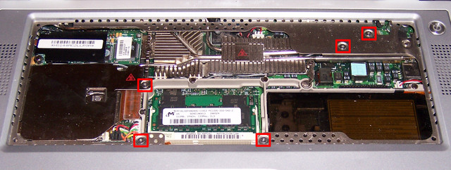
Reinstall the five T8 screws that hold the motherboard to the case. All five screws should be identical and short.
Finally, reconnect the keyboard cable, set the back end of the keyboard into the opening, and latch the front end of the keyboard into place.
Next: G4 550 Reassembly, Bottom Side
Sections
Background
Part 1: G4 500 Disassembly, Bottom Side
Part 2: G4 500 Disassembly, Top Side
Part 3: G4 500 Disassembly, Back Edge Screws
Part 4: G4 500 Disassembly, Removing the MB and Screen
Part 5: G4 550 Disassembly, Bottom Side
Part 6: G4 550 Disassembly, Top Side
Part 7: G4 550 Disassembly, Back Edge
Part 8: G4 550 Disassembly, Removing the MB and Screen
Part 9: G4 550 Reassembly, Screen
Part 10: G4 550 Reassembly, Motherboard
Part 11: G4 550 Reassembly, Top Side
Part 12: G4 550 Reassembly, Bottom Side
Aftereffects